Form Factors and Chipsets
A motherboard may also be called a planar board, system board, or main board. There are various types of motherboards that differ depending on the type of case that they fit in and the type of processor that they host. The form factor of the motherboard describes its general shape, what sorts of cases and power supplies it can use and its physical layout. A company can make 2 motherboards that have basically the same functionality but that use a different form factor and the only real differences will be the physical layout of the board and the position of the components. Common form factors have included AT, Baby AT, ATX, Mini ATX, LPX, Mini LPX and NLX. The table below contains more information:
Style
Where Found
Match to Case and
Power Supply
Full AT
Obselete
Full AT, Full Tower
Baby AT
Obselete
All except Slimline, ATX
LPX
Obselete
Slimline
Mini LPX
Obselete
Slimline
NLX
Old PCs (circa 1999)
Slimline
ATX
Newer PCs
ATX
MicroATX
Newer PCs
MicroATX/ATX
FlexATX
Newer PCs
FlexATX
Standard BTX
Newest form factor
BTX
MicroBTX
Newest form factor
MicroBTX
PicoBTX
Newest form factor
PicoBTX
NOTE: Laptop motherboards tend to be proprietary to the model for which they are designed.
Currently, the ATX form factor is the most widely used for new PCs. The BTX standard provides better airflow and cooling, specifically the thermal unit which blows hot air from the CPU directly out of the case. At this time, it is unknown if this form factor will take off or fade into oblivion.
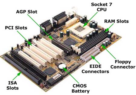
When first looking at a motherboard, you should see that the top side of the motherboard contains ports used for connecting various peripherals. Peripherals are composed of input and output devices including the mouse, keyboard, monitor, speakers, printer, etc. On the main face of the motherboard, we have our processor socket, RAM slots, FDD and HDD controllers, expansion slots and other features. Motherboards also contain configurable jumpers and possibly even DIP switches(typically on older models). These jumpers use BERG pins and a small connector that slides onto the pins to designate "on". BERG connectors are also used to connect the front panel LEDs and switches to the board. Below is a graphic that shows some of the common features of an ATX motherboard.
ATX System Board
Now that we have looked at form factors, we next need to discuss chipsets. The chipset of a motherboard defines the type of processor(s) that the motherboard can take, the type and size of RAM, and many other capabilities and features of the motherboard. For the most part, the chipset will also determine the configuration of USB and firewire ports, whether or not there is onboard sound, video, networking, and other features. Motherboard manufacturers may choose to make alterations outside the specifications of the chipset. Chipsets are made up of 2 main chips which are known as Northbridge and Southbridge. The Northbridge's duties are typically to facilitate the relationship between the processor and RAM and handle video, while the Southbridge handles storage and expansion devices. Popular chipset manufacturers include Intel, AMD, VIA technologies, and NVIDIA.
As a technician, you will need to know how to put together a computer that meets a customer's needs. For starters, you need to make sure that you have the right case for your motherboard, a processor with the right socket and speed for your motherboard, and the features that your customer wants. If the motherboard doesn't offer onboard sound and video, networking, etc., you will need to get expansion cards for these, or find a motherboard that does include these features. Similarly, when replacing a bad motherboard, you need to make sure that it is compatible with the rest of the system. If the customer frequently uses USB flash drives and other USB devices, you might want to get a system that offers front side USB ports, or a USB hub. If they are still using dial-up, you should be aware that many new systems no longer offer on board modems. You need to make sure that the case you choose fits the customer's environment. If the customer's desk only has 18 inches of clearance, then it wouldn't be a good idea to get a full tower case. The list could go on and on, but you probably get the idea.
Motherboard Installation
When working with internal components on a computer, don't forget to wear your anti-static wrist strap. Below are the steps for installing a motherboard.
Lay the case on its side with the open side facing up.
Insert the little risers with screw holes on one end into the holes on the back inside of the case. These little risers are called standouts and are used to elevate the motherboard off the back wall of the case. Make sure that the locations you have placed the standouts align with the screw holes on the motherboard. Some cases come with the standouts already installed.
Next, you might choose to install the RAM and CPU beforehand, or go ahead and put the motherboard in first.
Insert the motherboard into the case and screw it into the standouts.
If you have not already, install the CPU, CPU fan, and RAM.
Connect the power from the power supply to the motherboard.
Connect a monitor and boot the system. If you see the BIOS splash screen, you are probably in good shape.
Connect the wires for items such as the power button, reset button, power LED, system speaker, hard drive activity LED, front side USB, etc. These BERG connectors have a positive and negative side. If a particular item is not working, plug it in the other way.
Connect all drives and periperals.
Expansion Busses
As we all know, computers aren't "what you see is what you get" systems. Since their inception, they have provided a way to add functionality through the use of expansion slots to which expansion cards can be added. In order to accomodate expansion cards from various manufacturers, they needed to have a standard for them to adhere to, and thus, the expansion bus was born. The expansion bus provided a method for standardizing the physical characteristics and speed. With regards to speed, it should be noted that the expansion bus runs at a much slower speed than the system bus. Below is a look at the history of expansion busses.
Bus
Format
Notes
PC-bus
8 Bit
Used in PC and PC-AT models
ISA
16 bit
Runs at 8 or 8.33mhz
VESA
32 bit
Designed to address video limitations
EISA
32 bit
Supports Plug-and-Play and Bus mastering
MCA
32 bit
Supports PnP and Bus mastering
PCI
32/64 bit
Supports PnP, Burst Mode, Bus Mastering. Utilizes the host bridge to communicate with other types of expansion slots. The 32-bit version is the most common. Speed is 33MHZ
PCI-X
32/64 bit
Variation of PCI that provides much faster speeds and is backward compatible with traditional PCI. The 64-bit version is more common than the 32-bit.
AGP
32/64 bit
Variation of PCI only for video with a direct and faster connection to the Northbridge.
PCIe (PCI Express)
32 bit?
Variation of PCI that uses a full-duplex point-to-point serial connection to the Northbridge. Not backward compatible with other PCI technologies.
Currently, most new motherboards contain AGP, PCI, PCI-X and/or PCIe slots. PCI has dominated the market for some time and continues to do so. In addition to its faster speed of 33MHZ, one of the biggest selling points was its ability to self configure devices which was a beginning step in the emergence of Plug-and-Play. Now, new variations of PCI are being adopted such as PCI-X and PCIe. The main difference between PCI-X and the original PCI standard is speed. PCI-X offers 4 speed options: PCI-X 66, PCI-X 133, PCI-X 266, PCI-X 533.
PCIe is the latest and greatest technology and is a dramatic change in that it uses a full-duplex point-to-point serial (as opposed to the traditional parallel) connection directly to the Northbridge. This connection is known as a "link", and is built up from a collection of 1 or more lanes. All devices must minimally support a single-lane (x1) link. Devices may optionally support wider links composed of 2, 4, 8, 12, 16, or 32 lanes. The more lanes, the wider the PCIe slot and the faster the speeds. A PCIe card will physically fit (and work correctly) in any slot that is at least as large as it is (e.g. an x1 card will work in an x4 or x16 slot). PCIe 2.0 can theoretically achieve speeds of 16GBps in both directions when having 32 lanes.
System Resources
In previous versions of this study guide, this is where we would list tables of IRQs, I/O addresses, etc., that you would need to memorize. Now that the new exam no longer covers Windows 9x or Windows ME, we don't believe you will be tested on this information anymore. It is still probably important to know the following.
Devices in a computer utilize 4 categories of system resources as follows:
IRQ - The IRQ (interrupt request) value is an assigned location where the computer can expect a particular device to interrupt it when the device sends the computer signals about its operation.
I/O Address - Input/output addresses are resources used by virtually every device in a computer and represent locations in memory that are designated for use by various devices to exchange information between themselves and the rest of the PC. No devices share the same I/O address.
DMA - Direct Memory Access channels allow hardware devices (like sound cards or keyboards) to access the main memory without involving the CPU. This frees up CPU resources for other tasks.
Memory Address - In some situations an expansion card will have onboard RAM or ROM that needs to borrow memory from the system RAM so that the CPU can access it.
In the old days, system resources had to be manually configured and problems with IRQ and I/O conflicts were frequent. This is no longer an issue as these things have been completely automated.
The BIOS and CMOS Software Layer Model
Layer #
Layer
0
Hardware
1
BIOS
2
Operating System
3
Applications
BIOS stands for Basic Input/Output System and is a collection of small software programs that allow a CPU to talk to the hardware components of the PC. The BIOS resides on a system ROM chip categorized as firmware. Traditionally you could not make changes to ROM chips, however, all newer ones are flash ROM which means that they can be updated. BIOS services are accessed using software interrupts, which are similar to the hardware interrupts except that they are generated inside the processor by programs instead of being generated outside the processor by hardware devices.
BIOS routines begin when the computer is booted and are mad up of 3 main operations. Processor manufacturers program processors to always look in the same place in the system BIOS ROM for the start of the BIOS boot program. This is normally located at FFFF0h - right at the end of the system memory.
First, the Power On Self Tests (POST) are conducted. These tests verify that the system is operating correctly and will display an error message and/or output a series of beeps known as beep codes which vary depending on the BIOS manufacturer. If you don't have your system speaker connected, you will not hear the beep codes. The text and beep errors generated by the BIOS can be cryptic and sometimes a better solution is to use a Post Card. A post card plugs into an expansion slot and will generate a numerical code designating the component that was being tested when the failure occurred.
Second, is initialization in which the BIOS looks for the video card. In particular, it looks for the video card's built in BIOS program and runs it. The BIOS then looks for other devices' ROMs to see if any of them have BIOSes and they are executed as well.
Third, is to initiate the boot process. The BIOS looks for boot information that is contained in file called the master boot record (MBR) at the first sector on the disk. If it is searching a floppy disk, it looks at the same address on the floppy disk for a volume boot sector. Once an acceptable boot record is found the operating system is loaded which takes over control of the computer.
People often use the terms BIOS and CMOS interchangeably, but they are actually completely different. CMOS stands for Complimentary Metal Oxide Semiconductor and in the old days was a completely separate chip on the motherboard. Nowadays, it is often built into the southbridge. While the BIOS contains basic information that allows communication between the CPU and hardware, it cannot take into account all of the specific features and brands of hardware available. This is where the CMOS comes in. The CMOS setup program (AKA CMOS Setup Utility) is a program that allows us to access the information and settings stored on the CMOS chip. CMOS setup can be accessed by pressing a key or certain combination of keys right after booting the computer. The key or keys varies by BIOS manufacturer.
Once in the CMOS setup utility, you can view and change a wide variety of features for your hardware. These options will vary widely depending on your system, however, below are some of the common tasks you can perform:
Change the CPU voltage and multiplier. This is known as overclocking.
Change the system's date and time.
View and change floppy and hard drive settings.
Change the boot order of the PC. This is handy when you are installing an operating system with a bootable CD-ROM and need to change the boot order to boot from the CD-ROM drive first.
Enable, disable, and configure settings for parallel ports, serial ports, USB, etc.
Configure power management.
Configure a password to access CMOS setup. This can usually be cleared with jumper settings on the motherboard.
CMOS is also responsible for managing the system's date and time information as well. CMOS uses a battery to store this and the other configuration information. In newer systems, if the battery dies, CMOS is reset to factory default.
For more in depth information about the BIOS including the various setup utility settings, read The BIOS Companion.