This is our free study guide for CompTIA's Network+ certification exam (N10-004). If you would like to report an error or contribute additional information, please use the contact link at the bottom of the site, or post in our forums. We hope you find this guide useful in your studies.
Domain 1.0: Network Technologies
Domain 1.1: Common Networking Protocols
TCP - TCP breaks data into manageable packets and tracks information such as source and destination of packets. It is able to reroute packets and is responsible for guaranteed delivery of the data.
IP - This is a connectionless protocol, which means that a session is not created before sending data. IP is responsible for addressing and routing of packets between computers. It does not guarantee delivery and does not give acknowledgement of packets that are lost or sent out of order as this is the responsibility of higher layer protocols such as TCP.
UDP - A connectionless, datagram service that provides an unreliable, best-effort delivery.
ICMP - Internet Control Message Protocol enables systems on a TCP/IP network to share status and error information such as with the use of PING and TRACERT utilities.
SMTP - Used to reliably send and receive mail over the Internet.
FTP - File transfer protocol is used for transferring files between remote systems. Must resolve host name to IP address to establish communication. It is connection oriented (i.e. verifies that packets reach destination).
TFTP - Same as FTP but not connection oriented.
ARP - provides IP-address to MAC address resolution for IP packets. A MAC address is your computer's unique hardware number and appears in the form 00-A0-F1-27-64-E1 (for example). Each computer stores an ARP cache of other computers ARP-IP combinations.
POP3 - Post Office Protocol. A POP3 mail server holds mail until the workstation is ready to receive it.
IMAP - Like POP3, Internet Message Access Protocol is a standard protocol for accessing e-mail from your local server. IMAP (the latest version is IMAP4) is a client/server protocol in which e-mail is received and held for you by your Internet server.
TELNET - Provides a virtual terminal or remote login across the network that is connection-based. The remote server must be running a Telnet service for clients to connect.
HTTP - The Hypertext Transfer Protocol is the set of rules for exchanging files (text, graphic images, sound, video, and other multimedia files) on the World Wide Web. It is the protocol controlling the transfer and addressing of HTTP requests and responses.
HTTPS - Signifies that a web page is using the Secure Sockets Layer (SSL) protocol and is providing a secure connection. This is used for secure internet business transactions.
NTP - Network Time Protocol is a protocol that is used to synchronize computer clock times in a network of computers.
SNMP - Stands for Simple Network Management Protocol and is used for monitoring and status information on a network. SNMP can be used to monitor any device that is SNMP capable and this can include computers, printers, routers, servers, gateways and many more using agents on the target systems. The agents report information back to the management systems by the use of traps which capture snapshot data of the system. This trap information could be system errors, resource information, or other information. The SNMPv2 standard includes enhancements to the SNMPv1 SMI-specific data types, such as including bit strings, network addresses, and counters. In SNMPv3 security was addressed. Because all of the trap information sent was in clear text, any monitoring information being sent and collected for operational purposes could also be pulled off the wire by a malicious person
SIP Stands for Session Initiation Protocol and is a signaling protocol, widely used for controlling multimedia communication sessions such as voice and video calls over Internet Protocol (IP). Other feasible application examples include video conferencing, streaming multimedia distribution, instant messaging, presence information and online games. The protocol can be used for creating, modifying and terminating two-party (unicast) or multiparty (multicast) sessions consisting of one or several media streams. The modification can involve changing addresses or ports, inviting more participants, adding or deleting media streams, etc.
RTP Real-time Transport Protocol is the audio and video protocol standard used to deliver content over the Internet. RTP is used in conjunction with other protocols such as H.323 and RTSP.
IGMP Internet Group Management Protocol is used to manage Internet Protocol multicast groups. IP hosts and adjacent multicast routers use IGMP to establish multicast group memberships. IGMP is only needed for IPv4 networks, as multicast is handled differently in IPv6 networks.
TLS - Transport Layer Security is a cryptographic protocol that provides security for communications over networks such as the Internet. TLS and SSL encrypt the segments of network connections at the Transport Layer end-to-end. Several versions of the protocols are in wide-spread use in applications like web browsing, electronic mail, Internet faxing, instant messaging and voice-over-IP (VoIP).
Domain 1.2: Identify Commonly Used TCP/UDP Ports
Ports are what an application uses when communicating between a client and server computer. Some common ports are:
Protocol
Type
Number
FTP
TCP
20,21
SSH
TCP
22
TELNET
TCP
23
SMTP
TCP
25
DNS
TCP/UDP
53
DHCP
UDP
67
TFTP
UDP
69
HTTP
TCP
80
POP3
TCP
110
NTP
TCP
123
IMAP4
TCP
143
SNMP
UDP
161
HTTPS
TCP
443
Domain 1.3: Identify the Following Address Formats
IPv4 - Every IP address can be broken down into 2 parts, the Network ID(netid) and the Host ID(hostid). All hosts on the same network must have the same netid. Each of these hosts must have a hostid that is unique in relation to the netid. IP addresses are divided into 4 octets with each having a maximum value of 255. We view IPv4 addresses in decimal notation such as 124.35.62.181, but it is actually utilized as binary data.
IP addresses are divided into 3 classes as shown below:
Class
Range
A
1-126
B
<128-191
C
192-223
NOTE: 127.x.x.x is reserved for loopback testing on the local system and is not used on live systems. The following address ranges are reserved for private networks:
IPv6 - The previous information on TCP/IP has referred to IPv4, however, this addressing scheme has run out of available IP addresses due to the large influx of internet users and expanding networks. As a result, the powers that be had to create a new addressing scheme to deal with this situation and developed IPv6. This new addressing scheme utilizes a 128 bit address (instead of 32) and utilizes a hex numbering method in order to avoid long addresses such as 132.64.34.26.64.156.143.57.1.3.7.44.122.111.201.5. The hex address format will appear in the form of 3FFE:B00:800:2::C for example.
MAC Addressing - Also known as hardware address or ethernet address, A MAC address is a unique code assigned to most networking hardware. The hardware is assigned a unique number by the manufacturer and the address is permanently assigned to the device. MAC Addresses are in a 48-bit hexidecimal format such as 00:2f:21:c1:11:0a. They are used to uniquely identify a device on a network, and for other functions such as for being authenticated by a DHCP server. For more information, read MAC Addressing Formats And Broadcasts.
Domain 1.4: Proper Use of Addressing Technologies
Subnetting - IP addresses can be class A, B or C. Class A addresses are for networks with a large number of hosts. The first octet is the netid and the 3 remaining octets are the hostid. Class B addresses are used in medium to large networks with the first 2 octets making up the netid and the remaining 2 are the hostid. Class C is for smaller networks with the first 3 octets making up the netid and the last octet comprising the hostid. The Network ID and the Host ID are determined by a subnet mask. The default subnet masks are as follows:
Class
Default Subnet
Subnets
Hosts Per Subnet
Class A
255.0.0.0
126
16,777,214
Class B
255.255.0.0
16,384
65,534
Class C
255.255.255.0
2,097,152
254
What if you wanted more than 1 subnet? Subnetting allows you to create multiple logical networks that exist within a single Class A, B, or C network. If you don't subnet, you will only be able to use one network from your Class A, B, or C network. When subnetting is employed, the multiple networks are connected with a router which enables data to find its way between networks. On the client side, a default gateway is assigned in the TCP/IP properties. The default gateway tells the client the IP address of the router that will allow their computer to communicate with clients on other networks.
Classful versus Classless addressing the original TCP/IP addressing method described above was called classful addressing which worked by dividing the IP address space into chunks of different sizes called classes. Classless addressing is referred to as Classless Inter-Domain Routing (CIDR) and is done by allocating address space to Internet service providers and end users on any address bit boundary, instead of on 8-bit segments. So 172.16.50.0 does not have to use the standard subnet mask of 255.255.0.0 which makes a Class B address space and which also puts it on the same network as 172.16.51.0 using the subnet mask of 255.255.0.0. (With classful addressing, our example has 172.16 as the network name and the 50.0 and 51.0 ranges are both part of the same host naming convention). Instead, by using classless addressing 172.16.50.0/24 puts these systems on a different network than 172.16.51.0/24 because the network names here are 172.16.50 and 172.16.51 which are different.
NAT - NAT stands for Network Address Translation and is a commonly used IP translation and mapping technology. Using a device (such as a router) or piece of software that implements NAT allows an entire home or office network to share a single internet connection over a single IP address. A single cable modem, DSL modem, or even 56k modem could connect all the computers to the internet simultaneously. Additionally, NAT keeps your home network fairly secure from hackers. NAT is built in to the most common Internet Connection Sharing technologies.
PAT Port Address Translation is a feature of a network device that translates TCP or UDP communications made between hosts on a private network and hosts on a public network. It allows a single public IP address to be used by many hosts on a private network.
SNAT Secure Network Address Translation an extension of the standard Network Address Translation (NAT) service. SNAT is done through one to one IP address translation of one internal IP address to one external IP address where NAT is effectively one external address to many internal IP addresses.
DHCP - Dynamic Host Configuration Protocol provides a solution that automatically assigns IP addresses to computers on a network. When a client is configured to receive an IP address automatically, It will send out a broadcast to the DHCP server requesting an address. The server will then issue a "lease" and assign it to that client. Some of the benefits of DHCP include the following:
Prevents users from making up their own IP addresses.
Prevents incorrect gateway or subnet masks from being entered.
Decreases amount of time spent configuring computers especially in environments where computers get moved around all the time.
APIPA Stands for Automatic Private Internet Protocol Addressing. Client systems that are configured for automatic IP address assignment / dynamic IP assignment will attempt to use DHCP to make a request for an IP address lease for a given network. When the DHCP server is unavailable the service on the client will automatically configure the system with an APIPA IP address in the 169.254.0.1 through 169.254.255.254 address range with a subnet mask of 255.255.0.0.
Unicast - the sending of information packets to a single network node. This type of network transmission is used where a private or unique resource such as media servers are being requested for two way connections that are needed to complete the network communication. So in the media server example, a client system may make the request for streaming content from the single source and the responding system may leverage unicast as part of the response to the session request to deliver the content.
Multicast a single source address responding to multiple destination addresses with information to be sent. In a media server example, the single source address may need to send the data to multiple clients; it does this by sending the data with multiple destination IP addresses. All the clients that see this network traffic will check to see if it is meant for them with the supplied information. If it is not the client does not receive the data. If a network node does see that the data is intended for them the device will respond by receiving the packet.
Broadcast traffic sent out from a network node that will reach every other node on the subnet / broadcast domain because the message is sent with the intent of reaching all nodes. The network node that is sending the traffic will use the broadcast address for that subnet and every device in that broadcast domain will receive the broadcast information. Generally the broadcast address is the last IP address of that segment. As an example, in the IP address range of 192.168.0.0 this broadcast address would be 192.168.255.255 and the traffic would reach all available nodes on the subnet. Additionally 255.255.255.255 could be used which is the broadcast address of the zero network (0.0.0.0). Internet Protocol standards outline that the zero network stands for the local network so only those node on the local network would hear the broadcast traffic across the 255.255.255.255 address.
Domain 1.5: Common IPv4 and IPv6 Routing Protocols
Link State routing protocols are one of the two main classes of routing protocols used in packet switching networks and includes protocols such as Open Shortest Path First (OSPF) and Intermediate System to Intermediate System (IS-IS). The link-state protocol is performed on every router on the network, where every routing node constructs a map of the connectivity to the network by showing which nodes are connected to each other. Each router calculates the next best logical hop from it to every possible known destination which forms the node's routing table.
Open Shortest Path First (OSPF) is a dynamic routing protocol and is used on Internet Protocol (IP) based networks of all sizes large to small. OSPF is an interior gateway protocol (IGP) that routes IP packets within a single routing domain and was designed to support variable-length subnet masking (VLSM) and Classless Inter-Domain Routing (CIDR) addressing.
Intermediate System to Intermediate System (IS-IS) a link state protocol that operates by forwarding network topology information throughout a network of routers. Each router then independently builds a picture of the network's topology based on the data received and the best topological path through the network to the destination. IS-IS is an Interior Gateway Protocol (IGP) typically used on larger networks.
Distance-vector routing protocols are one of the two main classes of routing protocols used in packet switching networks and includes Routing Information Protocol (RIP) and Interior Gateway Routing Protocol (IGRP). uses distance as one factor and the vector as the other to determine against the known routing tables to deliver data to source and destination locations. Routers using the distance-vector routing protocol will update other routers of topology changes periodically when a change is detected in the topology of a network.
Routing Information Protocol (RIPv1) RIP is a distance-vector routing protocol using hop count as a routing metric. The maximum number of hops allowed for RIP is 15 which effectively limits the size of networks that RIP can support.
Routing Information Protocol (RIPv2) improved upon RIPv1 by having the ability to include subnet information with its updates which allows for Classless Inter-Domain Routing (CIDR) support. The 30 second proactive broadcast has been eliminated in favor of multicast advertisements for its updates. The 15 hop count limit remains so that the devices are backwards compatible with RIPv1 devices.
Border Gateway Protocol (BGP) is the core routing protocol of the Internet. It maintains a table of IP networks and the data that designates where and how to reach each network through autonomous systems (AS). BGP makes routing decisions based on path, network policies and / or rule sets.
Enhanced Interior Gateway Routing Protocol (EIGRP) a proprietary hybrid protocol from Cisco that is a distance vector routing protocol that functions like a link state routing protocol. EIGRP collects information and stores it in three tables; the Neighbor Table which stores the information about neighboring routers, the Topology Table which contains only the information and data regarding the routing tables from directly connected neighbors and the Routing table which stores the actual routes to all destinations.
Domain 1.6: The Purpose and Properties of Routing
Interior Gateway Protocol (IGP) routing protocol that is used within an autonomous system which is sometimes referred to as an administrative domain. One type of Interior Gateway Protocol are the Distance-vector routing protocols such as Routing Information Protocol (RIP), Interior Gateway Routing Protocol (IGRP) and Enhanced Interior Gateway Routing Protocol (EIGRP). Another type are the Link-state routing protocols such as Open Shortest Path First (OSPF) and Intermediate system to intermediate system (IS-IS)
Exterior Gateway Protocol (EGP) routing protocol that is used across different autonomous systems / administrative domains. It was the routing protocol leveraged for Internet connected devices in the early 1980s. Border Gateway Protocol (BGP) is the replacement standard for Internet routing over EGP.
Static Router Updates a router with manually configured routing tables. For these types of devices, a network administrator will manually build and make updates to the routing table for all routes in the administrative domain. Static routers are best suited for small internetworks; due to the need of the manual administration, they do not scale well to large networks where routing information is often changed, updated and appended. Static routers are not fault tolerant because when another network device goes down the manually input information may not necessarily provide alternate pathing to a destination which makes it unreachable (unless quick, manual administrative updates are made.)
Dynamic Router Updates A router with dynamically configured routing tables. This type of automatic configuration is made up of routing tables that are built and maintained by ongoing communication between the routers only (by default this does not include initial setup and configuration or administrative needs for a persistent route configuration). Dynamic routing is fault tolerant; if a router or link goes down, the routers sense the change in the network topology when the learned route expires in the routing table and cannot be renewed due to the outage. This change is then disseminated to other routers so that all the routers learn of the network changes. Routing Information Protocol (RIP) and Open Shortest Path First (OSPF) routing protocols for IP and RIP for IPX are some of examples of protocols that can be used for these dynamic updates.
Next Hop defined as the next place that a data packet needs to go. In most cases, routers do not need all of the information regarding where the originating source of the data transmission was. In most cases routers just need to know where there data needs to go next and the next referred to as the next hop because all they are trying to do is deliver it to the specified destination IP address that is included in the header information of the data being sent. If that router is the last hop and can deliver it to the specified IP address it does otherwise it refers to its routing tables to figure out which router to hand it off to in the effort to get the data packet where it needs to go.
Routing Tables sometimes referred to as a Routing Information Base (RIB), is the database information that stores all the rout information for the routing network devices. The routing table holds the route information regarding the topology of the network immediately around the device to other network destinations and it will often include the metric / cost associated for the route. There are three main route entries that are generally found in the routing tables - Network Route, Host Route and the Default Route. The Network Route is route to a specific Network ID on the network. The Host Route is a route to a specific network address. A Default route is the path used if a physical router or other network routing device cannot find a route for the specified destination.
Convergence achieved when all of the available topology information from routing devices have been passed along to all of the other deceives in totality and all when the information gathered is not in a contradiction state to any other router's informed topology information. When all of the network routing devices "agree" on what the network topology looks like it is said to have full convergence.
Domain 1.7: Characteristics of Wireless Standards
Wireless networks allow computers to comunicate without the use of cables using IEEE 802.11 standards, also known as Wi-Fi. A connection is made from a device, which is usually a PC or a Laptop with a wireless network interface card (NIC), and an Access Point (AP), which acts as a bridge between the wireless stations and Distribution System (DS) or wired networks. An 802.11 wireless network adapter can operate in two modes, Ad-Hoc and Infrastructure. In infrastructure mode, all your traffic passes through a wireless access point. In Ad-hoc mode your computers talk directly to each other and do not need an access point. The table below shows the various standards.
Standard
Speed
Distance
Frequency
802.11a
54 mbps
100 ft
5 GHz
802.11b
11 mbps
300 ft
2.4 GHz
802.11g
54 mbps
300 ft
2.4 GHz
802.11n
540 mbps
600 ft
5 GHz and/or 2.4 GHz
Authentication and Encryption:
WEP - Wired Equivalent Privacy is a security encryption algorithm that is easily cracked. For this reason, it has been replaced by other technologies.
WPA - The original WPA standard used TKIP, but was later replaced by WPA2 which uses a more secure AES-based algorithm. WPA uses a 256 bit key to encrypt data. This key may be entered either as a string of 64 hexadecimal digits, or as a passphrase of 8 to 63 characters. It is susceptible to brute force attacks when a weak passphrase is used.
RADIUS - Remote Authentication Dial In User Service (RADIUS) is a networking protocol that provides centralized Authentication, Authorization, and Accounting (AAA) management for computers to connect and use a network service. RADIUS is often used by ISPs and enterprises to manage access to the Internet or internal networks, and wireless networks. Microsoft's answer to corporate wireless security is the use of RADIUS authentication through its Internet Authentication Services (IAS) product.
TKIP - Temporal Key Integrity Protocol was designed as a solution to replace WEP without requiring the replacement of legacy hardware. TKIP suffered from similar flaws as WEP and has been replaced by more secure encryption schemes.
Domain 2.0: Network Media and Topologies
Domain 2.1: Standard Cable Types and Their Properties
Cable Types:
Type
Description
CAT3
Unshielded twisted pair capable of speeds up to 10Mbit/s. Used with 10Base-T, 100Base-T4, and 100Base-T2 Ethernet.
CAT4
Unshielded twisted pair capable of speeds up to 20Mbit/s. Not widely used. Used with 10Base-T, 100Base-T4, and 100Base-T2 Ethernet.
CAT5
Unshielded twisted pair capable of speeds up to 100Mbit/s. May be used with 10Base-T, 100Base-T4, 100Base-T2, and 100Base-TX Ethernet.
CAT5e
Enhanced Cat 5 is similar to CAT5, but exceeds its performance. Improved distance over previous categories from 100m to 350m. May be used for 10Base-T, 100Base-T4, 100Base-T2, 100BaseTX and 1000Base-T Ethernet.
CAT6
Can transmit data up to 220m at gigabit speeds. It has improved specifications for NEXT (Near End Cross Talk), PSELFEXT (Power Sum Equal Level Far End Cross Talk), and Attenuation. Cat 6 is backward compatible with lower Category grades and supports the same Ethernet standards as Cat 5e.
Multimode Fiber
Multimode fibers have large cores. They are able to carry more data than single mode fibers though they are best for shorter distances because of their higher attenuation levels.
Single Mode Fiber
Single Mode fibers have a small glass core. Single Mode fibers are used for high speed data transmission over long distances. They are less susceptible to attenuation than multimode fibers.
RG59 and RG6
These are both shielded coaxial cables used for broadband networking, cable television, and other uses.
Serial
A serial cable is a cable that can be used to transfer information between two devices using serial communication, often using the RS-232 standard. Typically use D-subminiature connectors with 9 or 25 pins. Cables are often unshielded, although shielding cables may reduce electrical noise radiated by the cable.
Shielded twisted pair (STP) - differs from UTP in that it has a foil jacket that helps prevent cross talk. Cross talk is signal overflow from an adjacent wire.
EMI - Electrical devices such as printers, air conditioning units, and television monitors can be sources of electromagnetic interference, or EMI. Some types of network media have more resistance to EMI than others. Standard UTP cable has minimal resistance to EMI, while fiber optic cable is highly resistant.
Plenum grade cabling - is required if the cabling will be run between the ceiling and the next floor (this is called the plenum). Plenum grade cabling is resistant to fire and does not emit poisonous gasses when burned.
Simplex - Signals can be passed in one direction only. Half Duplex - Half duplex means that signals can be passed in either direction, but not in both simultaneously. Full Duplex - Full duplex means that signals can be passed in either direction simultaneously.
Domain 2.2: Common Connector Types
BNC - This connector has found uses with both broadcast television equipment and computer networks. With regards to networking, this connector was used on early 10Base-2 (Thinnet) Ethernet networks. It has a center pin connected to the center coaxial cable conductor and a metal tube connected to the outer cable shield. A rotating ring outside the tube locks the cable to the female connector.
RJ-11 - Short for Registered Jack-11, a four or six-wire connector used primarily to connect telephone equipment in the United States (POTS). The cable itself is called category 1 (Cat 1) and is used for dial-up connections. Modems have rj-11 jacks that connect them to the wall outlet.
RJ-45 - Short for Registered Jack-45, it is an eight-wire connector used commonly to connect devices on Ethernet LANs. RJ-45 connectors look similar to RJ-11 connectors used for connecting telephone equipment, but they are larger.
ST - The ST connector is a fiber optic connector which uses a plug and socket which is locked in place with a half-twist bayonet lock. The ST connector was the first standard for fiber optic cabling. ST Connectors are half-duplex.
SC - The SC connector is a fiber optic connector with a push-pull latching mechanism which provides quick insertion and removal while also ensuring a positive connection. SC Connectors are half-duplex.
LC - The LC connector is just like a SC connector only it is half the size. Like SC connectors, LC connectors are half-duplex.
RS-232 - A standard for serial binary data interconnection between a DTE (Data terminal equipment) and a DCE (Data communication equipment). Commonly found in use with bar code scanners, measuring tools, and laboratory instruments are designed to interface to a computer using a standard RS232 serial cable connection. Many of these uses are being replaced with USB enabled devices. The connector is a DB-9 or DB-25 connector.
Domain 2.3: Common Physical Network Topologies
Star - The star topology uses twisted pair (10baseT or 100baseT) cabling and requires that all devices are connected to a hub. Advantages are centralized monitoring, and failures do not affect others unless it is the hub, easy to modify. The disadvantage is that the hub is a single point of failure. If it goes down, there are no communications possible.
Mesh - In a true mesh topology every node has a connection to every other node in the network. A full mesh provides redundancy in case of a failure between links, but is impractical due the complexity and the expensive amount of cabling required.
Bus - This topology is an old one and essentially has each of the computers on the network daisy-chained to each other. Packets must pass through all computers on the bus. This type is cheap, and simple to set up, but causes excess network traffic, a failure may affect many users, and problems are difficult to troubleshoot.
Ring - A ring topology has a physical and logical ring and is used on SONET and FDDI networks (note that Token Ring networks are actually a hybrid star ring topology). Any station can send a packet around the ring but only the station with the token can do so. The token is passed around the ring giving all stations an opportunity to communicate. This is a very fast and simple network. However if any part of the ring goes down, the entire LAN goes down. If there is a problem at a station, it may be difficult to locate it. Ring networks are not very common.
Point-to-point - This topology generally refers to a connection restricted to two endpoints. Point-to-point is sometimes referred to as P2P (not the same as peer-to-peer file sharing networks), or Pt2Pt, or variations of this. Examples of this topology include RS-232 serial connections as well as laser network connections between buildings.
Point-to-Multipoint - Also known as P2MP, this is a method of communication between a series of receivers and transmitters to a central location. The most common example of this is the use of a wireless access point that provides a connection to multiple devices.
Hybrid - Hybrid topologies are combinations of the above and are common on very large networks. For example, a star bus network has hubs connected in a row (like a bus network) and has computers connected to each hub as in the star topology.
Domain 2.4: Wiring Standards
568A and 568B - The number 568 refers to the order in which the individual wires inside a CAT 5 cable are terminated. The only difference between the two standards is that the green and orange pins are terminated to different pins. There is no difference in signal and both the 568A and 568B are used as patch cords for Ethernet connections.
Straight through vs Crossover - A straight through cable uses either the 568A or 568B wiring standard and is used for connecting devices to routers, hubs, switches, etc. An crossover cable is used to connect computing devices together directly (i.e. connecting 2 computers directly together). A crossover cable uses the 568A standard on one end and 568B on the other end.
Rollover - Rollover cable (also known as Cisco console cable) is a type of null-modem cable that is most commonly used to connect a computer terminal to a router's console port. This cable is typically flat and has a light blue color. It gets the name rollover because the pinouts on one end are reversed from the other, as if the wire had been rolled over and you were viewing it from the other side.
Loopback -
A loopback cable redirects the output back into itself and is used for troubleshooting purposes (loopback test). This effectively gives the NIC the impression that it is communicating on a network, since its able to transmit and receive communications.
Domain 2.5: WAN Technology Types and Properties
Frame Relay - Frame relay is a secure, private network that utilizes a logical path or virtual circuit to allocate bandwidth for high performance transmissions. Frame relay is the premier high-speed packet-switching protocol communicating data, imaging, and voice between multiple locations. Frame relay is available in a range of bandwidths from 56 Kbps to full T1 (1.54 Mbps).
T-1/T-3 - A T-1 is a dedicated phone connection supporting data rates of 1.544Mbps. A T-1 line actually consists of 24 individual channels, each of which supports 64Kbits per second. Each 64Kbit/second channel can be configured to carry voice or data traffic. Most telephone companies allow you to buy just some of these individual channels, known as fractional T-1 access. T-1 lines are a popular leased line option for businesses connecting to the Internet and for Internet Service Providers (ISPs) connecting to the Internet backbone. The Internet backbone itself consists of faster T-3 connections. T-1 comes in either copper or fiber optics.
ATM - ATM stands for Asynchronous Transfer Mode and is a high-speed, packet-switching technique that uses short fixed length packets called cells. ATM can transmit voice, video, and data over a variable-speed LAN and WAN connections at speeds ranging from 1.544Mbps to as high as 622Mbps. ATM is capable of supporting a wide range of traffic types such as voice, video, image and data.
SONET - SONET and SDH are a set of related standards for synchronous data transmission over fiber optic networks. SONET is short for Synchronous Optical NETwork and SDH is an acronym for Synchronous Digital Hierarchy. SONET is the United States version of the standard and SDH is the international version. SONET defines a base rate of 51.84 Mbps and a set of multiples of the base rate known as "Optical Carrier levels." (OCx). Speeds approaching 40 gigabits per second are possible.
ISDN - Integrated Services Digital Network (ISDN) is comprised of digital telephony and data-transport services offered by regional telephone carriers. ISDN involves the digitalization of the telephone network, which permits voice, data, text, graphics, music, video, and other source materials to be transmitted over existing telephone wires. There are 2 types of ISDN channels:
B (bearer) - Transfers data at 64Kbps. An ISDN usually contains 2 B channels for a total of 128kbps.
D (data) - Handles signalling at either 16Kbps or 64Kbps(sometimes limited to 56Kbps) which enables the B channel to strictly pass data
Connection
Speed
Medium
ISDN BRI
64kbps/channel
Twisted-pair
ISDN PRI
1,544kbps
Twisted-pair
POTS
Up to 56 Kbps
Twisted pair
PSTN
64kbps/channel
Twisted-pair
Frame Relay
56kbps-45mbps
Varies
T-1
1.544 Mbps
Twisted-pair, coaxial, or optical fiber
ADSL
256Kbps to 24Mbps (ADSL 2+)
Twisted-pair
SDSL
1.544mbps
Twisted-pair
VDSL
100mbps
Twisted-pair
Cable modem
512 Kbps to 52 Mbps
Coaxial
Satellite
1gbps (avg 1-5mbps)
Air
T-3
44.736 Mbps
Twisted-pair, coaxial, or optical fiber
OC-1
51.84 Mbps
Optical fiber
OC-3
155.52 Mbps
Optical fiber
Wireless
1gbps
Air
ATM
10gbps
Optical fiber
SONET
10gbps
Optical fiber
Packet and Circuit Switching - Packet switching refers to protocols in which messages are divided into packets before they are sent. Each packet is then transmitted individually and can even follow different routes to its destination. Once all the packets forming a message arrive at the destination, they are recompiled into the original message. Most modern Wide Area Network (WAN) protocols, including TCP/IP and Frame Relay are based on packet-switching technologies. In contrast, normal telephone service is based on a circuit-switching technology, in which a dedicated line is allocated for transmission between two parties. Circuit-switching is ideal when data must be transmitted quickly and must arrive in the same order in which it is sent. This is the case with most real-time data, such as live audio and video. Packet switching is more efficient and robust for data that can withstand some delays in transmission, such as e-mail messages and Web pages.
Domain 2.6: LAN Technology Types and Properties
Ethernet - Ethernet is the most widely-installed local area network ( LAN) technology. Specified in a standard, IEEE 802.3, Ethernet was originally developed by Xerox from an earlier specification called Alohanet (for the Palo Alto Research Center Aloha network) and then developed further by Xerox, DEC, and Intel. Early ethernet networks uses coaxial connections. The most common types currently use twisted pair cabling, however, fiber optic cabling is becoming much more common as standards and speeds increase. Below are some of the ethernet standards:
Connection Type
Cable Type
Connector
Maximum Length
Speed
10Base-T
Category 3 or better UTP cable
RJ-45
100 meters (328 ft)
10 mbps
100Base-TX
Cat 5 twisted pair
RJ-45
100 meters (328 ft)
100 mbps
100Base-FX
Fiber Optic
ST, SC
2000 meters
100 mbps
1000Base-T
CAT5e or higher
RJ-45
100 meters (328 ft)
1 gbps
1000Base-LX
Laser over fiber
SC
Up to 5000 meters
1 gbps
1000Base-SX
Short wavelength laser over fiber
SC
Up to 550 meters
1 gbps
1000Base-CX
Twinax or short haul copper
9-Pin shielded D-subminiature connector, or
8-pin ANSI fiber channel type 2 (HSSC) connector.
25 meters
1 gbps
10GBASE-SR
Shortwave laser over multi-mode fiber optics
LC, SC
300 meters
10 Gbps
10GBASE-LR
Laser over single-mode fiber optics
LC, SC
2000 meters
10 Gbps
10GBASE-ER
Laser over either single or multi-mode fiber
LC, SC
40 kilometers
10 Gbps
10GBASE-SW
Shortwave laser over multi-mode fiber optics
LC, SC
300 meters
10 Gbps
10GBASE-LW
Laser over single-mode fiber optics
LC, SC
2000 meters
10 Gbps
10GBASE-EW
Laser over either single or multi-mode fiber
LC, SC
40 kilometers
10 Gbps
10GBASE-T
Cat 5e (or higher) twisted pair
RJ-45
100 meters (328 ft)
10 Gbps
CSMA/CD (Carrier Sense Multiple Access with Collision Detection) - In the early days of ethernet, when two hosts would send packets at the same time, a collision would occur. A standard had to be created that would have the hosts follow rules relating to when they could send data and when they could not. This standard is Carrier Sense Multiple Access with Collision Detection, referred to as CSMA/CD. CSMA/CD forces computers to listen to the wire before sending in order to make sure that no other host on the wire is sending. If a collision is detected, both of the senders will send a jam signal over the Ethernet. This jam signal indicates to all other devices on the Ethernet segment that there has been a collision, and they should not send data onto the wire. How Ethernet CSMA/CD Works
Bonding (AKA Link Aggregation, Port Trunking, EtherChannel, etc.) - Uses multiple network cables/ports in parallel to increase the link speed beyond the limits of any one single cable or port, and to increase the redundancy for higher availability.
Domain 2.7: Common Logical Network Topologies
Peer to Peer - A peer to peer network is one in which lacks a dedicated server and every computer acts as both a client and a server. This is a good networking solution when there are 10 or less users that are in close proximity to each other. A peer to peer network can be a security nightmare, because the people setting permissions for shared resources will be users rather than administrators and the right people may not have access to the right resources. More importantly the wrong people may have access to the wrong resources, thus, this is only recommended in situations where security is not an issue. P2P file sharing networks work under a similar architecture, however, there are differences between them and the LAN networking architecture.
Client/Server - This type of network is designed to support a large number of users and uses dedicated server/s to accomplish this. Clients log in to the server/s in order to run applications or obtain files. Security and permissions can be managed by 1 or more administrators which who set permissions to the servers' resources. This type of network also allows for convenient backup services, reduces network traffic and provides a host of other services that come with the network operating system.
VPN - A virtual private network is one that uses a public network (usually the Internet) to connect remote sites or users together. Companies use site to site VPN to support critical applications to connect offices to remote users. Instead of using a dedicated, real-world connection such as leased line, a VPN uses "virtual" connections routed through the Internet from the company's private network to the remote site or employee.
VLAN - A virtual LAN is a local area network with a definition that maps workstations on a basis other than geographic location (for example, by department, type of user, or primary application). The virtual LAN controller can change or add workstations and manage load-balancing and bandwidth allocation more easily than with a physical picture of the LAN. Network management software keeps track of relating the virtual picture of the local area network with the actual physical picture.
Domain 2.8: Install components of Wiring Distribution
Vertical Cross Connect is a location within a building where cables originate and / or are terminated, reconnected using jumpers or pass throughs or are connected to patch panels or other similar devices where the locations are from upper or lower floors in the building. These cables could be of multiple different types and mediums such as phone networks, data lines, copper based, fiber channel, etc.
Horizontal Cross Connect similar to Vertical Cross Connect locations; these are within a building where cables originate and / or are terminated but these locations are all on the same floor or building level. As with Vertical Cross Connect configurations, these locations can be of multiple different network types and mediums.
Patch Panel wall or rack mounted collection of data connections where all of the network media converges. These rooms are generally some form of telecommunications closet in a facility and it is used to connect all of the different types of incoming and outgoing media types on the LAN. When they all span the same floor of a building they are sometimes referred to as Horizontal Cross Connect locations and when they span different levels of a location / different floors of a building they are sometimes referred to as Vertical Cross Connect locations. The main Patch Panel room will often be the connection point for the LAN to be connected to the WAN and / or the internet.
66 Block is a legacy type of punch down block used to connect sets of 22 through 26 American Wire Gauge (AWG) solid copper wire in a telephone system. They have a 25-pair standard non-split capacity and generally are unsuited for traffic and data network communications above 10 megabits per second (Mbps).
Main Distribution Frame (MDF) is a wire distribution frame for connecting equipment inside a facility to cables and subscriber carrier equipment outside of the facility. One example of this is where all of the phone cabling inside a facility is run to planned phone locations (e.g. offices) back to the MDF. When the local telephone company makes the external connections then all circuits are completed.
Intermediate Distribution Frame (IDF) is another place much like a Horizontal Cross Connect location or a Vertical Cross Connect location where network administrators can physically change the network media around and where they can house other needed network equipment such as routers, switches, repeaters and so forth.
25 Pair is a grouping of 25 pairs of wires all inside a single covering / housing or outer insulation casing. It is best suited for telephone / voice cable runs rather than data cable runs and is generally used as a feeder cable.
100 Pair is a larger cabling segment to its 25 pair cousin but used in the same manner; all of the 100 pairs of wires are inside a single covering / housing or outer insulation casing. It is best suited for telephone / voice cable runs rather than data cable runs and is generally used as a feeder cable.
110 Block is the more modern replacement of the legacy 66 Block and is used as a wiring distribution point for wired telephone systems (voice) and other types of wired networking (data). On one side of the block wires are punched down into RJ-11 connectors for voice and RJ-45 connectors for data communications.
Demarc is the point of operational and administrative control change in a network. One example of this is the Main Distribution Frame (MDF) point in a facility. This is where the wire distribution frame for connecting equipment inside a facility to cables and subscriber carrier equipment outside of the facility occurs and this is considered a demarcation point of the operational control of the internal systems where it changes over to the control of the external presence.
Demarc Extension where the end of the line of the external administrative control is extended beyond that actual endpoint. Example you are one business inside of a large high rise building on the 15th floor only and the Main Distribution Frame (MDF) point is on the ground floor. Your responsibility probably ends at the Intermediate Distribution Frame (IDF) on your floor and the external administration (example Phone Company) ends at the Main Distribution Frame (MDF) on the ground floor. The building administration owns all the cabling responsibility between the Main Distribution Frame (MDF) on the ground floor and your Intermediate Distribution Frame (IDF) on your floor. That cabling is effectively the Demarc Extension
Smart Jack is a network connection device that is used to connect your internal network to an external service provider network. The device handles all of the code and protocol differences between the two networks and is often the actual demarcation point between the two service entities.
Wiring Installation is the physical installation of internal wiring in a facility. This may be the pulls of copper phone and data lines to the running of fiber optic medium from the different cross connect locations.
Wiring Termination is the end point of networked cable runs that will generally end either in a patch panel or a jack location in an office. This has historically been the copper wire runs associated with phone lines to the RJ-11 jacks / blocks to the data lines on the RJ-45 connections. Wire termination is also a consideration on fiber optic pulls as well which requires a higher set of skill level.
Domain 3.0: Network Devices
Domain 3.1: Common Network Devices
Hub - A physical layer network device used to connect multiple Ethernet devices together. Active hubs act as a repeater and boost the signal in order to allow for it to travel farther, while passive hubs simply pass the signal through. Most hubs have an uplink port that allows them to connect to other hubs, a router, or other network devices.
Repeater: - A physical layer device that boosts signals in order to allow a signal to travel farther and prevent attenuation. Attentuation is the degradation of a signal as it travels farther from its origination. Repeaters do not filter packets and will forward broadcasts. Both segments must use the same access method, which means that you can't connect a token ring segment to an Ethernet segment. Repeaters can connect different cable types as shown in the image.
Modem - The modem is a device that converts digital information to analog by MODulating it on the sending end and DEModulating the analog information into digital information at the receiving end. Most modern modems are internal, however, they can be internal or external. External modems are connected to the back of the system board via a RS-232 serial connection. Internal modems are installed in one of the motherboard's PCI or ISA expansion slots depending on the modem. The modem contains an RJ-11 connection that is used to plug in the telephone line. Modems have different transmission modes as follows:
Simplex - Signals can be passed in one direction only.
Half Duplex - Half duplex means that signals can be passed in either direction, but not in both simultaneously. Half-duplex modems can work in full-duplex mode.
Full Duplex - Full duplex means that signals can be passed in either direction simultaneously.
Modems can also be classified by their speed which is measured by the BAUD rate. One baud is one electronic state change per second. Since a single state change can involve more than a single bit of data, the Bits Per Second(BPS) unit of measurement has replaced it as a better expression of data transmission speed. Common modem speeds are V.34 at 28.8 kbps, V.34+ at 33.6 kbps and V.90 at 56 Kbps.
Network Interface Card - A Network Interface Card, often abbreviated as NIC, is an expansion board you insert into a computer so the computer can be connected to a network. Most NICs are designed for a particular type of network, protocol and media, although some can serve multiple networks.
Media Converters - simple networking devices that make it possible to connect two dissimilar media types such as twisted pair with fiber optic cabling. They were introduced to the industry nearly two decades ago, and are important in interconnecting fiber optic cabling-based systems with existing copper-based, structured cabling systems. They are also used in MAN access and data transport services to enterprise customers. Fiber media converters support many different data communication protocols including Ethernet, Fast Ethernet, Gigabit Ethernet, T1/E1/J1, DS3/E3, as well as multiple cabling types such as coax, twisted pair, multi-mode and single-mode fiber optics. Media converter types range from small standalone devices and PC card converters to high port-density chassis systems that offer many advanced features for network management.
Switch - A switch is a network device that filters and forwards packets between LAN segments and ensures that data goes straight from its origin to its proper destination. Switches remember the address of every node on the network, and anticipate where data needs to go. A switch only operates with the computers on the same LAN. This reduces competition for bandwidth between devices on the network. It isn't smart enough to send data out to the internet, or across a WAN. These functions require a router.
Bridge - Functions the same as a repeater, but can also divide a network in order to reduce traffic problems. A bridge can also connect unlike network segments (ie. token ring and ethernet). Bridges create routing tables based on the source address. If the bridge can't find the source address it will forward the packets to all segments. Bridging methods:
Transparent - Only one bridge is used.
Source-Route - Bridging address tables are stored on each PC on the network
Spanning Tree - Prevents looping where there exists more than one path between segments
Wireless Access Point - A Wireless Access Point is a radio frequency transceiver which allows your wireless devices to connect to a network. The WAP usually connects to a wired network, and can relay data between the wireless devices (such as computers or printers) and wired devices on the network. A wireless access point will support up to 32 wireless devices. The range of the wireless signal depends greatly on obstructions such as walls. For more information about wireless standards, see domain 1.7.
Router - Functioning at the network later of the OSI model, a router is similar to a switch, but it can also connect different logical networks or subnets and enable traffic that is destined for the networks on the other side of the router to pass through. Routers create or maintain a table of the available routes and can be configured to use various routing protocols to determine the best route for a given data packet. Routers can connect networks that use disimilar protocols. Routers also typically provide improved security functions over a switch.
Firewall - Either a hardware or software entity (or a combination of both) that protects a network by stopping network traffic from passing through it. In most cases, a firewall is placed on the network to allow all internal traffic to leave the network (email to the outside world, web access, etc.), but stop unwanted traffic from the outside world from entering the internal network. This is achieved by granting and denying access to resources based on a set of configurable rules.
DHCP Server - A server that is responsible for assiging unique IP address to the computers on a network. A DHCP server prevents the assignment of duplicate IP addresses to clients and reduces administrative effort in network configuration. A DHCP server is actually more of a service that is found on network operating systems such as Windows 2002/2008 server, or on network devices such as routers.
Domain 3.2: Specialized Network Devices
Multilayer Switch - A multilayer switch (MLS) is a computer networking device that switches on OSI layer 2 like an ordinary network switch and provides extra functions on higher OSI layers. Some MLSs are also able to route between VLAN and/or ports like a common router. The routing is normally as quick as switching (at wirespeed). Some switches can use up to OSI layer 7 packet information; they are called layer 4-7 switches, content-switches, web-switches or application-switches.
Content Switch - The main function of a content switch is to inspect the network data that it receives so that it can decide where on the network that data (or request) needs to be forwarded to. Once this is determined the data is sent to the appropriate server which can handle the data. In most cases the switch looks to see what type of application or software the request is targeted at. It does this by looking to see what port the requests is directed at. For example if the data is targeted at an ftp port then the request will be sent to an ftp sever. The main benefit of this approach is that the switch acts as a load balancer as it can balance data or requests across the different type of application servers used by the business. A second major function that this type of switch can perform is to look at the incoming requests and see which websites are targeted. This is important for large enterprises or hosting companies. If for example a web hosting company was hosting several thousand websites the switch could direct requests to the specific servers that the websites are running on. These devices tend to be very expensive.
IDS/IPS - These terms stand for Intrusion Detection System and Intrusion Prevention System respectively. IDS is a device (or application) that monitors network and/or system activities for malicious activities or policy violations. IDS is a passive system that gives alerts when something suspicious is detected and logs the events into a database for reporting. IPS, on the other hand, sits inline with traffic flows on a network, actively shutting down attempted attacks as theyre sent over the wire. It can stop the attack by terminating the network connection or user session originating the attack, by blocking access to the target from the user account, IP address, or other attribute associated with that attacker, or by blocking all access to the targeted host, service, or application. Vendors are increasingly combining the two technologies into a single box, now referred to as IDPS. These devices are used with, not instead of, a firewall.
Load Balancer - A load balancer is a hardware and/or software solution that provides load balancing services. Load balancing is used to distribute workloads evenly across two or more computers, network links, CPUs, hard drives, or other resources, in order to get optimal resource utilization, maximize throughput, minimize response time, and avoid overload. Using multiple components with load balancing, instead of a single component, may increase reliability through redundancy. As an example, Google receives many, many more search requests than a single server could handle, so they distribute the requests across a massive array of servers.
Mutlifunction Network Devices - As you might guess, multifunction network devices combine the function of individual devices into a single unit. An example is wireless access points which often include one or more of the following: firewall, DHCP server, wireless access point, switch, gateway, and router.
DNS Server - DNS is an Internet and networking service that translates domain names into IP addresses. The internet is based on numerical IP addresses, but we use domain names because they are easier to remember. DNS is the service that looks up the IP address for a domain name allowing a connection to be made. This process is very similar to calling information. You call them with a name, they check their database and give you the phone number. The DNS service is included with server operating systems (Windows 2003/2008, Linux, etc.) and network devices such as routers.
Bandwidth Shaper - Describes the mechanisms used to control bandwidth usage on the network. Bandwidth shaping is typically done using software installed on a network server. From this server, administrators can control who uses bandwidth, for what, and when. Bandwidth shaping establishes priorities to data traveling to and from the Internet and within the network.
A bandwidth shaper essentially performs two key functions: monitoring and shaping. Monitoring includes identifying where bandwidth usage is high and at what time of day. After that information is obtained, administrators can customize or shape bandwidth usage for the best needs of the network. I am unaware why CompTIA listed this in the "network devices" section of their objectives, but bandwidth shapers are typically software.
Proxy Server - A proxy server acts as a middle-man between clients and the Internet providing security, administrative control, and caching services. When a user makes a request for an internet service and it passes filtering requirements, the proxy server looks in its local cache of previously downloaded web pages. If the item is found in cache, the proxy server forwards it to the client. This reduces bandwidth through the gateway. If the page is not in the cache, the proxy server will request the page from the appropriate server. Nowadays, the functions of proxy servers are often built into firewalls.
CSU/DSU - A Channel Service Unit/Data Service Unit (CSU/DSU) acts as a translator between the LAN data format and the WAN data format. Such a conversion is necessary because the technologies used on WAN links are different from those used on LANs. Although CSU/DSU's look similar to modems, they are not modems, and they don't modulate or demodulate between analog and digital. All they really do is interface between a 56K, T1, or T3 line and serial interface (typically a V.35 connector) that connects to the router. Many newer routers have CSU/DSUs built into them.
Domain 3.3: Advanced Features of a Switch
PoE - Generally speaking, Power over Ethernet technology describes a system to safely pass electrical power, along with data, on Ethernet cabling. Standard versions of PoE specify category 5 cable or higher. Power can come from a power supply within a PoE-enabled networking device such as an Ethernet switch or from a device built for "injecting" power onto the Ethernet cabling. IP Phones, LAN access points, and WiFi switches to RFID readers and network security cameras. All of these require more power than USB offers and very often must be powered over longer runs of cable than USB permits. In addition, PoE uses only one type of connector, an 8P8C (RJ45), whereas there are four different types of USB connectors.
Spanning Tree Protocol - Spanning Tree is one of three bridging methods a network administrator can use. Which method you use usually will be determined by the networks size. The simplest method is transparent bridging, where only one bridge or switch exists on the network. The next is Source-Route, in which bridging address tables are stored on each PC on the network. Then theres what you came for, spanning tree, which prevents loops where there exists more than one path between segments. STP was upgraded to Rapid Spanning Tree Protocol (RSTP).
VLAN - A broadcast domain is normally created by the router. With VLANs, a switch can create the broadcast domain. This allows a virtual network, independent of physical location to be created.
Trunking - VLANs are local to each switch's database, and VLAN information is not passed between switches. Trunk links provide VLAN identification for frames traveling between switches. The VLAN trunking protocol (VTP) is the protocol that switches use to communicate among themselves about VLAN configuration.
Port Mirroring - Used on a network switch to send a copy of network packets seen on one switch port (or an entire VLAN) to a network monitoring connection on another switch port. This is commonly used for network appliances that require monitoring of network traffic, such as an intrusion-detection system.
Port Authentication - The IEEE 802.1x standard defines 802.1x port-based authentication as a client-server based access control and authentication protocol that restricts unauthorized clients from connecting to a LAN through publicly accessible ports. The authentication server validates each client connected to a switch port before making available any services offered by the switch or the LAN.
Domain 3.4: Implement a Basic Wireless Network
Install Client the actual steps taken to set up a computer, laptop or other network connected device to the network. This may be in the form of just getting it correctly configured to use TCP/IP or more involved such as installing a software suite so that specific network parameters can be leveraged for proper connectivity to network resources or resources on the domain.
Network Connections Dialog Box used to configure different aspects of the network connections by way of a graphical user interface (GUI) within the Microsoft Windows operating systems (Windows XP, Windows Vista, Server 2003, etc). With respect to peer to peer networks, you can use the Network Tasks pane to Create a New Connection, Set up a Home or small office network as well as change the Windows Firewall settings and view available wireless networks.
Wireless Network Connection Dialog Box the graphical user interface (GUI) within the Microsoft Windows operating systems used to configure the wireless devices and their settings. On the General tab you can configure the specific hardware settings (parameters, drivers, etc) as well as the protocols (e.g. TCP/IP) and the network client that the device will use (e.g. Client for Microsoft Networks). Additionally, you can install services from this screen as well (e.g. Virtual Machine Network Service). The Wireless Networks tab will show you the available networks and allow you to configure preference for each of the networks encountered.
Access Point Placement correctly positioning your Wireless Access Points will allow for the seamless use of wireless devices on your network. By correctly placing the devices, users will not generally experience signal loss of their connection to the network. It is important to understand that there are many things that affect the wireless access point signal with respect to broadcast and receiving strength that include the construction and architecture of the building where the devices are distributed as well as general disruption of the frequency range that the access points operate on by other devices (e.g. microwave ovens, cordless phones, etc).
Physical Locations of Wireless Access Points (WAPs) device placement best practices include planning for more than just nominal half distances between devices. Consideration needs to be given to what type of obstructions may be currently in the way (physical fire breaks in between walls; metal superstructure, etc) as well as future plans to subdivide offices. Electrical motors and other higher current carrying lines need to be considered as well to keep interference to a minimum.
Wired or Wireless Connectivity planning for WAP to WAP connections only or a mix of wired and wireless connections. Its easier to connect WAP to WAP in a daisy chain signal relay configuration but when you do this you need to realize that a physical failure in one WAP device may take out all the devices. It is more work and it costs more in time money and effort to connect the WAPs using wired connections back to a switch or a router but it greatly reduces the potential connectively loss on the network; the loss of a single WAP where the WAPs are wired back results in only impacting the users of that one WAP instead of all WAPs up and downstream.
Install Access Point another term for the Wireless Access Point(s) that will allow you to correctly gain access to the network with your device. This point onto the network will allow the client device to configure itself with the necessary encryption (if required) and any other network required settings or else risk being defaulted off the network.
Configuring Encryption with respect to wireless clients these are the settings most commonly used. Disabled simply means that everything is passed as clear text. Wired Equivalent Privacy (WEP) is the lowest form of the types of encryption available and is generally only used today to allow legacy devices that cannot handle more robust encryption protocols to gain somewhat secured access to the network. WEP has been challenged and defeated for a number of years mainly due to the increase in computing power and the fact that the keys are alphanumeric or hexadecimal characters that are configured in 40 bit, 64 bit, 128 bit, 153 bit and 256 bit strength. Wi Fi Protected Access (WPA) was created by the Wi-Fi Alliance to better secure wireless networks and was created in response to the weaknesses researchers found in Wired Equivalent Privacy (WEP). Temporal Key Integrity Protocol (TKIP) is used in WPA to encrypt the authentication and encryption information that was initially passed on the wire in clear text before a network node could secure its communications on the network. Wi Fi Protected Access version 2 (WPA2) offers additional protection because it uses the strongest authentication and encryption algorithms available in the Advanced Encryption Standard (AES).
Configuring Channels and Frequencies most wireless routers work in the 2.4GHz frequency range and require network administrators to set up the channels for the devices to use. 1, 6 and 11 are the main channels used because they generally will not be interfered with from other devices such as cordless phones and Bluetooth devices that also work at this frequency range.
Setting ESSID and Beacon Extended Service Set identifier (ESSID) is the advertisement from the Wireless Access Point that basically announces its availability for network devices to make a connection. The announcement signal that is sent out is called the beacon.
Verifying Installation - the process that is outlined for making sure that all the settings needed to connect a network node to the wireless device. The best practice steps generally include on initial installation of the Wireless Access Point (WAP) to do so without any security to verify that a client can get on the network. Once that is successful you would then incorporate the security protocol that you wanted to use and to make sure the client can operate on the network again. Once this is successfully done it is assumed all other network nodes would be able to successfully repeat the same steps to access the network securely and with the traffic encrypted.
Domain 4.0: Network Management
Domain 4.1: OSI Model
The OSI networking model is divided into 7 layers. Each layer has a different responsibility, and all the layers work together to provide network data communication.
Layer
Description
Application
Represents user applications, such as software for file transfers, database access, and e-mail. It handles general network access, flow control, and error recovery. Provides a consistent neutral interface for software to access the network and advertises the computers resources to the network.
Presentation
Determines data exchange formats and translates specific files from the Application layer format into a commonly recognized data format. It provides protocol conversion, data translation, encryption, character-set conversion, and graphics-command expansion.
Session
Handles security and name recognition to enable two applications on different computers to communicate over the network. Manages dialogs between computers by using simplex(rare), half-duplex or full-duplex. The phases involved in a session dialog are as follows: establishment, data-transfer and termination.
Transport
Provides flow control, error handling, and is involved in correction of transmission/reception problems. It also breaks up large data files into smaller packets, combines small packets into larger ones for transmission, and reassembles incoming packets into the original sequence.
Network
Addresses messages and translates logical addresses and names into physical addresses. It also manages data traffic and congestion involved in packet switching and routing. It enables the option of specifying a service address (sockets, ports) to point the data to the correct program on the destination computer.
Data Link
The interface between the upper "software" layers and the lower "hardware" Physical layer. One of its main tasks is to create and interpret different frame types based on the network type in use. The Data Link layer is divided into two sub-layers: the Media Access Control (MAC) sub-layer and the Logical Link Control (LLC) sub-layer.
LLC sub-layer starts maintains connections between devices (e.g. server - workstation).
MAC sub-layer enables multiple devices to share the same medium. MAC sub-layer maintains physical device (MAC) addresses for communicating locally (the MAC address of the nearest router is used to send information onto a WAN).
Physical
The specification for the hardware connection, the electronics, logic circuitry, and wiring that transmit the actual signal. It is only concerned with moving bits of data on and off the network medium. Most network problems occur at the Physical layer.
Here is an idiotic, yet easy way to remember the 7 layers. Memorize the following sentence: All People Seem To Need Data Processing. The first letter of each word corresponds to the first letter of the layers starting with Application and ending with the physical layer.
Domain 4.3: Evaluate the Network Based on Configuration Management Documentation
The topics covered in this section are either already covered elsewhere, or are too expansive for the purposes of this guide. Consult your book(s) for more information about these topics.
Domain 4.4: Conduct Network Monitoring to Identify Performance and Connectivity Issues
The topics covered in this section are either already covered elsewhere, or are too expansive for the purposes of this guide. Consult your book(s) for more information about these topics.
Domain 4.5: Explain Different Methods and Rationales for Network Performance Optimization
Quality of Service - (QoS) is a set of parameters that controls the level of quality provided to different types of network traffic. QoS parameters include the maximum amount of delay, signal loss, noise that can be accommodated for a particular type of network traffic, bandwidth priority, and CPU usage for a specific stream of data. These parameters are usually agreed upon by the transmitter and the receiver. Both the transmitter and the receiver enter into an agreement known as the Service Level Agreement (SLA). In addition to defining QoS parameters, the SLA also describes remedial measures or penalties to be incurred in the event that the ISP fails to provide the QoS promised in the SLA.
Traffic Shaping (also known as "packet shaping" or ITMPs: Internet Traffic Management Practices) is the control of computer network traffic in order to optimize or guarantee performance, increase/decrease latency, and/or increase usable bandwidth by delaying packets that meet certain criteria. More specifically, traffic shaping is any action on a set of packets (often called a stream or a flow) which imposes additional delay on those packets such that they conform to some predetermined constraint (a contract or traffic profile).Traffic shaping provides a means to control the volume of traffic being sent into a network in a specified period (bandwidth throttling), or the maximum rate at which the traffic is sent (rate limiting), or more complex criteria such as GCRA. This control can be accomplished in many ways and for many reasons; however traffic shaping is always achieved by delaying packets. Traffic shaping is commonly applied at the network edges to control traffic entering the network, but can also be applied by the traffic source (for example, computer or network cardhttp://en.wikipedia.org/wiki/Traffic_shaping - cite_note-2) or by an element in the network. Traffic policing is the distinct but related practice of packet dropping and packet marking.
Load Balancing - is a technique to distribute workload evenly across two or more computers, network links, CPUs, hard drives, or other resources, in order to get optimal resource utilization, maximize throughput, minimize response time, and avoid overload. Using multiple components with load balancing, instead of a single component, may increase reliability through redundancy. The load balancing service is usually provided by a dedicated program or hardware device (such as a multilayer switch or a DNS server).
High Availability - (aka Uptime) refers to a system or component that is continuously operational for a desirably long length of time. Availability can be measured relative to "100% operational" or "never failing." A widely-held but difficult-to-achieve standard of availability for a system or product is known as "five 9s" (99.999 percent) availability.
Since a computer system or a network consists of many parts in which all parts usually need to be present in order for the whole to be operational, much planning for high availability centers around backup and failover processing and data storage and access. For storage, a redundant array of independent disks (RAID) is one approach. A more recent approach is the storage area network (SAN).
Some availability experts emphasize that, for any system to be highly available, the parts of a system should be well-designed and thoroughly tested before they are used. For example, a new application program that has not been thoroughly tested is likely to become a frequent point-of-breakdown in a production system.
Cache Engine - (aka server) is a dedicated network server or service acting as a server that saves Web pages or other Internet content locally. By placing previously requested information in temporary storage, or cache, a cache server both speeds up access to data and reduces demand on an enterprise's bandwidth. Cache servers also allow users to access content offline, including media files or other documents. A cache server is sometimes called a "cache engine."
A cache server is almost always also a proxy server, which is a server that "represents" users by intercepting their Internet requests and managing them for users. Typically, this is because enterprise resources are being protected by a firewall server. That server allows outgoing requests to go out but screens all incoming traffic. A proxy server helps match incoming messages with outgoing requests. In doing so, it is in a position to also cache the files that are received for later recall by any user. To the user, the proxy and cache servers are invisible; all Internet requests and returned responses appear to be coming from the addressed place on the Internet. (The proxy is not quite invisible; its IP address has to be specified as a configuration option to the browser or other protocol program.)
Fault-tolerance - describes a computer system or component designed so that, in the event that a component fails, a backup component or procedure can immediately take its place with no loss of service. Fault tolerance can be provided with software, or embedded in hardware, or provided by some combination.
In the software implementation, the operating system provides an interface that allows a programmer to "checkpoint" critical data at pre-determined points within a transaction. In the hardware implementation (for example, with Stratus and its VOS operating system), the programmer does not need to be aware of the fault-tolerant capabilities of the machine.
At a hardware level, fault tolerance is achieved by duplexing each hardware component. Disks are mirrored. Multiple processors are "lock-stepped" together and their outputs are compared for correctness. When an anomaly occurs, the faulty component is determined and taken out of service, but the machine continues to function as usual.
Parameters Influencing QOS
Bandwidth - is the average number of bits that can be transmitted from the source to a destination over the network in one second.
Latency - (AKA "lag") is the amount of time it takes a packet of data to move across a network connection. When a packet is being sent, there is "latent" time, when the computer that sent the packet waits for confirmation that the packet has been received. Latency and bandwidth are the two factors that determine your network connection speed. Latency in a packet-switched network is measured either one-way (the time from the source sending a packet to the destination receiving it), or round-trip (the one-way latency from source to destination plus the one-way latency from the destination back to the source). Round-trip latency is more often quoted, because it can be measured from a single point. Note that round trip latency excludes the amount of time that a destination system spends processing the packet. Many software platforms provide a service called ping that can be used to measure round-trip latency. Ping performs no packet processing; it merely sends a response back when it receives a packet (i.e. performs a no-op), thus it is a relatively accurate way of measuring latency.
Where precision is important, one-way latency for a link can be more strictly defined as the time from the start of packet transmission to the start of packet reception. The time from the start of packet transmission to the end of packet transmission at the near end is measured separately and called serialization delay. This definition of latency depends on the throughput of the link and the size of the packet, and is the time required by the system to signal the full packet to the wire.
Some applications, protocols, and processes are sensitive to the time it takes for their requests and results to be transmitted over the network. This is known as latency sensitivity. Examples of latency sensitive applications include VOIP, video conferencing, and online games. In a VOIP deployment, high latency can mean an annoying and counterproductive delay between a speakers words and the listeners reception of those words. Network management techniques such as QoS, load balancing, traffic shaping, and caching can be used individually or combined to optimize the network and reduce latency for sensitive applications. By regularly testing for latency and monitoring those devices that are susceptible to latency issues, you can provide a higher level of service to end users.
Jitter - Jitter is the deviation in or displacement of some aspect of the pulses in a high-frequency digital signal. As the name suggests, jitter can be thought of as shaky pulses. The deviation can be in terms of amplitude, phase timing, or the width of the signal pulse. Another definition is that it is "the period frequency displacement of the signal from its ideal location." Among the causes of jitter are electromagnetic interference (EMI) and crosstalk with other signals. Jitter can cause a display monitor to flicker; affect the ability of the processor in a personal computer to perform as intended; introduce clicks or other undesired effects in audio signals, and loss of transmitted data between network devices. The amount of allowable jitter depends greatly on the application.
Packet Loss - is the failure of one or more transmitted packets to arrive at their destination. This event can cause noticeable effects in all types of digital communications.
The effects of packet loss:
In text and data, packet loss produces errors.
In videoconference environments it can create jitter.
In pure audio communications, such as VoIP, it can cause jitter and frequent gaps in received speech.
In the worst cases, packet loss can cause severe mutilation of received data, broken-up images, unintelligible speech or even the complete absence of a received signal.
The causes of packet loss include inadequate signal strength at the destination, natural or human-made interference, excessive system noise, hardware failure, software corruption or overburdened network nodes. Often more than one of these factors is involved. In a case where the cause cannot be remedied, concealment may be used to minimize the effects of lost packets.
Echo - is when portions of the transmission are repeated. Echoes can occur during many locations along the route. Splices and improper termination in the network can cause a transmission packet to reflect back to the source, which causes the sound of an echo. To correct for echo, network technicians can introduce an echo canceller to the network design. This will cancel out the energy being reflected.
High Bandwidth Applications - A high bandwidth application is a software package or program that tends to require large amounts of bandwidth in order to fulfill a request. As demand for these applications continues to increase, bandwidth issues will become more frequent, resulting in degradation of a network system. One way to combat the effects of these applications on a network is to manage the amount of bandwidth allocated to them. This allows users to still use the applications without degrading the QoS of network services.
Examples:
Thin Clients
Voice over IP
Real Time Video
Multi-media
Domain 4.6: Implement the Following Network Troubleshooting Methodology
Gather Information on the Problem
In a contact center network, problems are typically discovered and reported by one of the following types of users:
External customers dialing into a call center to order products, obtain customer service, and so forth.
Internal agents receiving incoming calls from a call queue or initiating outbound collection calls to customers.
Internal users using administrative phones to call employees in other company locations or PSTN destinations, and perform basic actions such as call transfers and dialing into conferences.
As the network administrator, you must collect sufficient information from these users to allow you to isolate the problem. Detailed, accurate information will make this task easier. As you turn up your network, you may consider putting these questions in an on-line form. A form will encourage users to provide more details about the problem and also put them into the habit of looking for particular error messages and indicators. Capturing the information electronically will also permit you to retrieve and re-examine this information in the future, should the problem repeat itself.
Identify The Affected Area
Determine if the problem is limited to one workstation, or several workstations, one server, one segment, or the entire network. If only one person is experiencing a certain problem, the problem is most likely at the workstation. If groups of workstations are affected, the problem might lie at a part of the network that users all have in common, such as a particular software application or database, a server, the network segment, or the network configuration.
Determine If Anything Has Changed
To determine what has changed, ask question such as:
Could you do this task before? If this is a new task, perhaps the user needs different sysetm permissions, or additional hardware of software.
If you could do it before, when did you first notice you couldnt do it anymore? Try do find out what happened just before the problem came up, or at least try to pinpoint the time, since the source of the problem might be related to other changes elsewhere on the network.
What has changed since the last time you were able to do this task? Users can give you information about events that mightaffect their local systems. You can help them with leading questions such as, Did someone add something to your computer? or Did you do something differently this time?.
Establish The Most Probable Cause
T o establish the most probable cause, use a systematic approach. Eliminate possible causes, starting with the obvious and simplest one and working back through other causes. Do not overlook straightforward and smple corrections that can fix a range of problems and do not cost much time or effort to try. You might find you can resolve the issue on the spot.
Determine If Escalation Is Necessary
While troubleshooting a network problem, you might find the cause of the problem is not an issue that can be resolved over the phone or at the users desktop. It may be necessary to contact a fellow employee who has specialized knowledge, or a more senior administrator with the appropriate permissions and authoration. In these cases, the problem should be escalated to the appropriate personel to be resolved as quickly as possible.
Create an Action Plan and Solution, Identifying Potential Effect
Once you have determined the probable cause, you should create an action plan before changes are made, detailing each step taken while attempting to resolve the issue. One should also be certain that the original state (before troubleshooting) can be returned to in case things do not go as planned. Also consider the how the plan will affect the user or other aspects of the network. Thinking ahead can help ensure productivity doesnt suffer and that downtime is minimized.
Implement and Test the Solution
Implement the action plan step by step to fix the problem. If multiple changes are made at once, you will be unable to verify exactly what effect each adjustment had. Be sure to document each step because you can lose sight of what you have tried in complex troubleshooting scenarios.
Test the solution. Make sure the solution implemented actually solves the problem and didnt cause any new ones. Use several options and situations to conduct the tests. Sometimes testing over time is needed to ensure the solution is the correct one.
Identify the Results and Effects of the Solution
Verify that the user agrees that the problem is solved before you proceed with final documentation and closing the request. Even if the problem is solved, and the solution was well thought- out and documented, there might cascading effects elsewhere on the local system or on the network. Test for this before closing out the issue. If a major change was made, it is advisable to continue monitoring and testing for several days or even weeks after the problem appears to be resolved.
Document the Process and Solution
Document the problem and process used to arrived at the solution. Maintain the records as part of an overall documentation plan. This will provide and ever-growing database of information specific to your network and also it will be valuable reference material for future troubleshooting instances .especially if the problem is specific to the organization. Creating a troubleshooting template with required information included in all trouble reports will ensure all trouble reports are accurate and consistent no matter who completes them.
Domain 4.7: Troubleshoot Common Connectivity Issues and Select an Appropriate Solution
Crosstalk
Symptoms: Slow network performance and/or an excess of dropped or unintelligible packets. In telephony applications, users hear pieces of voice or conversations from a separate line.
Causes: Generally crosstalk occurs when two cables run in parallel and the signal of one cable interferes with the other. Crosstalk can also be caused by crossed or crushed wire pairs in twisted pair cabling.
Resolution: the use of twisted pair cabling or digital signal can reduce the effects of crosstalk. Maintaining proper distance between cables can also help.
Near-End Crosstalk
Symptoms: Signal loss or interference
Causes: Near-end crosstalk is crosstalk that occurs closer along the cable to the transmitting end. Often occurs in or near the terminating connector.
Resolution: Test with cable tester from both ends of the cable and correct any crossed or crushed wires. Verify that the cable is terminated properly and that the twists in the pairs of wires are maintained.
Attenuation
Symptoms: Slow response from the network.
Causes: Attenuation is the degradation of signal strength.
Resolution: Use shorter cable runs, add more access points, and/or add repeaters and signal boosters to the cable path. Or, evaluate the environment for interference. The interference you would look for would depend on the spectrum used.
Collisions
Symptoms: High latency, reduced network performance, and intermittent connectivity issues.
Causes: Collisions are a natural part of Ethernet networking as nodes attempt to access shred resources.
Resolution: Depends on the network. For example, replacing a hub with a switch will often solve the problem.
Shorts
Symptoms: Electrical shortscomplete loss of signal.
Causes: Two nodes of an electrical circuit that are meant to be at different voltages create a low- resistance connection causing a short circuit.
Resolution: Use a TDR to detect and locate shorts. Replace cables and connectors with known working ones.
Open Impedance Mismatch
Symptoms: Also known as echo, the tell-tale sign of open mismatch is an echo on either the talker or listener end of the connection.
Causes: The mismatching of electrical resistance.
Resolution: Use a TDR to detect impedance. Collect and review data,interpret the symptoms, and determine the root cause in order to correct the cause.
Interference
Symptoms: Crackling, humming, and static are all signs of interference. Additionally, low throughput, network degradation, and poor voice quality are also symptoms of interference.
Causes: RFI can be caused by a number of devices including cordless phones, Blue-Tooth devices, cameras, paging systems, unauthorized access points, and clients in ad-hoc mode.
Resolution: Remove or avoid environmental interferences as much as possible. This may entail simply turning off competing devices. Ensure there is adequate LAN coverage. To resolve problems proactively, test areas prior to deployment using tools such as spectrum analyzers.
Port Speed
Symptoms: No or low speed connectivity between devices.
Causes: Ports are configured to operate at different speeds and are therefore incompatible with each other.
Resolution: Verify that equipment is compatible and operating at the highest compatible speeds. For example, if a switch is running at 100 Mbs, but a computers NIC card runs at10 Mbs, the computer will run at the slower speed (10 Mbs). Replace the card with one that runs at 100 Mbs and throughput will be increased to the higher level (or at least higher levels since there are variables such as network congestion, etc.)
Port Duplex Mismatch
Symptoms: Late collisions, alignment errors, and FCS errors are present during testing.
Causes: Mismatches are generally caused by configuration errors. These occur when the switch port and a device are configured to use a different duplex setting or when both ends are set to auto-negotiate the setting.
Resolution: Verify that the switch port and the device are configured to use the same duplex setting. This may entail having to upgrade one of the devices.
Incorrect VLAN
Symptoms: No connectivity between devices.
Causes: Devices are configured to use different VLANs
Resolution: Reconfigure devices to use the same VLAN.
Incorrect IP Address
Symptoms: No connectivity between devices.
Causes: Either the source or destination device has an incorrect IP address.
Resolution: Use the ping command to determine if there is connectivity between devices. Resolution will depend on the problem. If a network is running a rouge DHCP server, for example, two computers could have leased the same IP address. Check TCP/IP configuration information using ipconfig /all on Window machines and ifconfig on Linux/UNIX/Apple machines. In that case troubleshoot DHCP (it may be off line, etc.). It could be the case that a static IP address was entered incorrectly. Check IP addresses; empty the arp cache on both computers.
Wrong Gateway
Symptoms: No connectivity between devices.
Causes: The IP address of the gateway is incorrect for the specified route.
Resolution: Change the IP address of the gateway to the correct address.
Wrong DNS
Symptoms: No connectivity between devices.
Causes: A device is configured to use the wrong DNS server.
Resolution: Open the network properties on a Windows machine. Open TCP/IP properties and check the IP address of the DNS server listed for the client. Put in the correct IP address. Test for connectivity.
Wrong Subnet Mask
Symptoms: No connectivity between devices.
Causes: Either the source or destination device has an incorrect subnet mask.
Resolution: Use the ping command to determine if there is connectivity between devices. Check the IP address on both devices. Change the incorrect subnet mask to a correct subnet mask. Test for connectivity.
Issues that should be IDd but Escalated
Switching Loop: Need spanning tree protocol to ensure loop free topologies.
Routing Loop: Packets are routed in a circle continuously.
Route Problems: Packets dont reach their intended destination. This could be caused by a number of things: configuration problems, convergence (in which you have to wait for the discovery process to complete), or a broken segment (a router is down, etc.).
Proxy arp: If mis-configured, DoS attacks can occur.
Broadcast Storms: The network becomes overwhelmed by constant broadcast traffic.
Wireless Connectivity Issues
Interference
Symptoms: Low throughput, network degradation, dropped packets, intermittent connectivity, and poor voice quality are all symptoms caused by interference.
Causes: RFI can be caused by cordless phones, Bluetooth devices, cameras, paging systems, unauthorized access points, metal building framing, and clients in ad-hoc mode.
Resolution: Remove or avoid environmental interferences as much as possible.
Incorrect Encryption
Symptoms: For wireless, if encryption levels between two devices (access point and client) do not match, connection is impossible. Similarly, if different encryption keys are used between to devices they cant negotiate the key information for verification and decryption in order to initiate communication.
Causes: Improper configuration.
Resolution: Ensure that security settings match between and among devices.
Congested Channel
Symptoms: Very slow speeds.
Causes: Interference from neighboring wireless network; congested network channel.
Resolution: Many wireless routers are set to auto configure the wireless channel. Try logging into the router and manually change the channel the wireless router is operating on.
Incorrect Frequency
Symptoms: No connectivity.
Causes: In wireless, devices must operate on the same frequency. A device for a 802.11a frequency cant communicate with one designed for 802.11b.
Resolution: Deploy devices that operate on the same frequency.
ESSID Mismatch
Symptoms: No connectivity between devices.
Causes: Devices are configured to use different ESSIDs.
Resolution: Set the devices to use the same SSID. Ensure that the wireless client and the access point are the same. Note: SSIDs are case sensitive.
Standard Mismatch
Symptoms: No connectivity between devices.
Causes: Devices are configured to use different standards such as 802.11a/b/g/n.
Resolution: Devices have to be chosen to work together. 802.11a, for example, is incompatible with 802.11b/g because the first operates at 5 GHz and the second at 2.4 GHz. O a 802.11g router could be set only for g mode and you are trying to connect with a 802.11b wireless card. Change the mode on the router.
Distance
Symptoms: Slow connection and low throughput.
Causes: The distance between two points may be to blame for this connectivity issue. The longer the distance between the two points the prominent the problem may become. Issues that can occur between the two points include latency, packet loss, retransmission, or transient traffic.
Resolution: I f the issue is with cabling, do not exceed distance limitations. If the issue is with wireless, you may need to increase coverage. Use a spectrum analyzer to determine coverage and signal strength.
Bounce
Symptoms: No or low connectivity between devices.
Causes: Signal from device bounces off obstructions and is not received buy the receiving device.
Resolution: If possible, move one device or the other to avoid obstructions. Monitor performance and check for interference.
Incorrect Antenna Placement
Symptoms: No or low signal and connectivity.
Causes: The position of the access points antenna can negatively affect overall performance.
Resolution: Change the position of the antenna and monitor device performance.
Domain 5.0: Network Tools
Domain 5.1: Command Line Interface Tools
Traceroute - A command-line troubleshooting tool that enables you to view the route to a specified host. This will show how many hops the packets have to travel and how long it takes. In Windows operating systems, the command used is "tracert".
IPCONFIG - This command is used to view network settings from a Windows computer command line. Below are the ipconfig switches that can be used at a command prompt.
ipconfig /all will display all of your IP settings.
ipconfig /renew forces the DHCP server, if available to renew a lease.
ipconfig /release forces the release of a lease.
IFCONFIG - IFCONFIG is a Linux/Unix command line tool that is similar to IPCONFIG in Windows. Common uses for ifconfig include setting an interface's IP address and netmask, and disabling or enabling a given interface. At boot time, many UNIX-like operating systems initialize their network interfaces with shell-scripts that call ifconfig. As an interactive tool, system administrators routinely use the utility to display and analyze network interface parameters.
PING - PING (Packet InterNet Groper) is a command-line utility used to verify connections between networked devices. PING uses ICMP echo requests that behave similarly to SONAR pings. The standard format for the command is ping ip_address/hostname. If successful, the ping command will return replies from the remote host with the time it took to receive the reply. If unsuccessful, you will likely recieve and error message. This is one of the most important tools for determining network connectivity between hosts.
ARP (Address Resolution Protocol) - A host PC must have the MAC and IP addresses of a remote host in order to send data to that remote host, and it's ARP that allows the local host to request the remost host to send the local host its MAC address through an ARP Request. Guide To ARP, IARP, RARP, and Proxy ARP
ARP PING (ARPING) - ARPING is a computer software tool that is used to discover hosts on a computer network. The program tests whether a given IP address is in use on the local network, and can get additional information about the device using that address. The arping tool is similar in function to ping, which probes hosts using the Internet Control Message Protocol at the Internet Layer (OSI Layer 3). Arping operates at the Link Layer (OSI Layer 2) using the Address Resolution Protocol (ARP) for probing hosts on the local network (link) only, as ARP cannot be routed across gateways (routers). However, in networks employing repeaters that use proxy ARP, the arping response may be coming from such proxy hosts and not from the probed target.
NSLOOKUP - This is a command that queries a DNS server for machine name and address information. Originally written for Unix operating systems, this command is now available on Windows and other operating systems. To use nslookup, type "nslookup" followed by an IP address, a computer name, or a domain name. NSLOOKUP will return the name, all known IP addresses and all known aliases (which are just alternate names) for the identified machine. NSLOOKUP is a useful tool for troubleshooting DNS problems.
Hostname - The hostname command is used to show or set a computer's host name and domain name. It is one of the most basic of the network administrative utilities. A host name is a name that is assigned to a host (i.e., a computer connected to the network) that uniquely identifies it on a network and thus allows it to be addressed without using its full IP address. Domain names are user-friendly substitutes for numeric IP addresses.
Dig (domain information groper) - Dig is a Linux/Unix tool for interrogating DNS name servers. It performs DNS lookups and displays the answers that are returned from the name server(s) that were queried.
Mtr - Mtr is a Linux command line tool that combines the functionality of the traceroute and ping programs in a single network diagnostic tool.
Route - The route command is used to display and manipulate a local routing table. Examples of its use include adding and deleting a static route. This tool is available in Unix, Linux and Windows.
NBTSTAT - Is a Windows utility used to troubleshoot connectivity problems between 2 computers communicating via NetBT, by displaying protocol statistics and current connections. NBTSTAT examines the contents of the NetBIOS name cache and gives MAC address.
NETSTAT - Is a Windows, Linux, and Unix command-line tool that displays network connections (both incoming and outgoing), routing tables, and a number of network interface statistics. It is used for finding problems in the network and to determine the amount of traffic on the network as a performance measurement.
Domain 5.2: Network Scanners
Packet Sniffers - A packet sniffer is a device or software used to capture packets traveling over a network connection. The packets are logged and can be decoded in order to provide information and statistics about the traffic on the network or network segment. These tools are used for troubleshooting difficult network problems, monitoring network traffic, and detecting intrusion attempts. Also known as Packet Analyzers.
Intrusion Detection Software - This was covered earlier in domain 3.1.
Intrusion Prevention Software - This was covered earlier in domain 3.1.
Port Scanners - A port scanner is a program designed to probe network hosts for open ports. This is often used by administrators to verify security policies of their networks and by attackers to identify running services on a host that can be exploited to gain access.
Domain 5.3: Hardware Tools
Cable Testers - Cable testers are electronic devices used to test a cable's integrity by checking for opens and shorts which can cause connectivity problems.
Protocol Analyzers - This tool is used to monitor network traffic and display packet and protocol statistics and information. As far as we're concerned, it is pretty much the same thing as a packet sniffer. Most tools sold today combine the functions of the listening device (packet sniffer) and the analytical device (packet analyzer).
Certifiers - Certifiers are a tool that tests cables in order to ensure that they will perform the job intended. This includes checking the speed loads that it can handle.
TDR (Time Domain Reflectometer) - Sends a signal down a cable and measures the distance that the signal travelled before bouncing back (like sonar). Used to find opens and shorts in cables.
OTDR (Optical Time Domain Reflectometer) - Similar to the TDR above, however, this is used to test fiber optic cables with light.
Multimeter - A multimeter, also known as a volt/ohm meter, is an electronic measuring instrument used to measure voltage, current and resistance.
Toner Probe - Most will detect opens and shorts like a cable tester, but this tool is mainly used to locate the termination points of cables.
Butt Set - A portable telephone that connects to a line using alligator clips and is used to test telephone circuits.
Punch Down Tool - A punch down tool is used to connect cabling such as telephone and ethernet to wall jacks.
Cable Stripper - Fairly self explanatory. A tool used to strip the jackets off of cables in order to expose the wire that can be connected to connectors or wall jacks.
Snips - Special scissors used for cutting cable.
Voltage Event Recorder - Captures and logs electrical current information for devices which can then be accessed on a PC. Mostly used for mission critical devices such as those found in a hospital.
Temperature Monitor - We aren't entirely sure what CompTIA is referring to with this. There are all kinds of temperature monitors from CPU temperature monitoring software to devices that monitor the temperature of a server room.
Domain 6.0: Network Security
Domain 6.1: Hardware and Software Security Devices
The topics covered in this section are already covered elsewhere in this guide.
Domain 6.2: Firewalls
Application Layer vs. Network Layer An application layer firewall works at the application layer of a protocol stack. (This is true for both the OSI model and the Internet Protocol Suite (TCP/IP)) Sometimes referred to as a proxy-based firewall or proxy server, it can be software running on a computer or server or as a stand-alone piece of hardware. The main function of the application layer firewall is to analyze traffic before passing it to a gateway point. A network layer firewall is sometimes referred to as a packet filter and these will operate at the network layer. The devices will not allow packets to pass the firewall unless they match the rule set as configured by the firewall administrator. Network layer firewalls can be either stateful or stateless.
Stateful vs. Stateless Stateful firewalls maintain pertinent information about any active sessions they have will speed packet processing using this information. This might include source and destination IP address, UDP or TCP ports, and other details about the connection such as the session initiation, type of data transfer and so forth. With Stateful processing if a packet does not match a currently established connection, it will be evaluated according to the rule set for new connections. If it does match it will be allowed to pass without needing to be compared to the rule sets in use. Stateless firewalls treat all of the packets on the network in isolation and independently from all of the other traffic on the wire. They have no way to know if any given packet is part of an existing connection, is trying to establish a new connection, or is just a rogue packet.
Scanning Services the process that is used by all firewalls to review the packets that are passing through them. Sometimes they will just review the header information or they may be configured to look at the data as well. More advanced firewalls might also combine virus detection and / or other forms of malware detection as part of their scanning process to halt the transmission of suspect packets through the device.
Content Filtering generally used at the application level to restrict or prevent access to websites that are not approved for work use, to block sites with objectionable material, or on a corporate black list for one reason or another. Content could be filtered in many different ways from suspect keywords, images on the site, downloadable files present, or site content labeling as defined by the website host itself (e.g. an adult site that defines itself as such the content filter would review the site content level and apply the filter).
Signature Identification a method of indentifying certain types of traffic based on a known behavior of that traffic. A firewall would know based on the signature definition comparison whether the traffic should be allowed to pass as permitted (e.g. http traffic or DNS traffic) or whether to deny traffic (e.g. repeated attempts to connect to multiple systems from multiple sessions, appearing as a possible Distributed Denial of Service (DDoS) attack.
Zones demarcation points from one network type to another. Networks internal to a company are considered internal zones or intranets. A network external to the internal network is generally considered the internet or external zones. If there is a network that the company manages that is not a part of the internal intranet but is in place between the intranet and the internet this is called the demilitarized zone or the DMZ. The main purpose of this zone is to act as an additional layer of security buffer between the intranet and the internet.
Domain 6.3: Network Access Security
ACL (Access Control List) - An ACL is a table in an operating system or network device (such as a router) that denies or allows access to resources.
MAC Filtering - This method controls access based on the unique MAC address assigned to all network devices.
IP Filtering - This method controls access based on the IP addresses (or a range of addresses) of network devices.
SSL VPN (Secure Sockets Layer virtual private network) - This is a VPN that runs on SSL and is accessible via https over a web browser. It allows users to establish secure remote access sessions from virtually any Internet connected browser. Unlike a traditional VPN, this method does not require the use of IPSec. The benefit of this solution is that it allows clients to access a corporate network from nearly anywhere which is not practical with a typical VPN.
VPN (Virtual Private Network) - A VPN is a network that uses a public telecommunication infrastructure, such as the Internet, to provide remote offices or individual users with secure access to their organization's network. A VPN works by using the shared public infrastructure while maintaining privacy through security procedures and tunneling protocols such as the Layer Two Tunneling Protocol (L2TP) or IPSec. In effect, the protocols, by encrypting data at the sending end and decrypting it at the receiving end, send the data through a "tunnel" that cannot be "entered" by data that is not properly encrypted.
L2TP (Layer 2 Tunneling Protocol) - L2TP is an extension of the Point-to-Point Tunneling Protocol (PPTP) used on VPNs. L2TP merges the best features of two other tunneling protocols: PPTP from Microsoft and L2F from Cisco Systems. As a tunnelling protocol, L2TP does not include encryption, but is often used with IPsec provide VPN connections from remote users to a remote network.
IPSec (Internet Protocol Security) - IPsec is a protocol suite that ensures confidentiality, integrity, and authenticity of data communications across a public network by authenticating and encrypting each IP packet of a data stream. IPSEC is made of two different protocols: AH and ESP. AH (Authentication header) is responsible for authenticity and integrity, while ESP (Encapsulating Security payload) encrypts the payload. IPSec is often used in conjunction with L2TP on VPNs.
RAS (Remote Access Service) - RAS refers to any combination of hardware and software to enable remote access to a network. A RAS server is a specialized computer which aggregates multiple communication channels together. An example of this would be a server that dial-up users dial into. The term was originally coined by Microsoft during the Windows NT era and is now called Routing and Remote Access Service (RRAS).
RDP (Remote Desktop Protocol) - Originally released with Windows NT 4.0 Terminal Services, RDP 4.0 allowed users to connect to a computer and remotely control (AKA Shadow) it. With the release of Windows Vista and upcoming Windows Longhorn, version 6.0 will allow one to connect to specific applications rather than the entire desktop of the remote computer. Remote Desktop allows systems administrators to remotely connect to a user's computer for technical support purposes, or connect to a server for maintenance and administration purposes. By default, RDP uses TCP port 3389.
PPPoE (Point to Point Protocol over Ethernet) - In the past, most internet users were connected to the internet via a serial modem using PPP, however, current technologies have replaced dial-up internet connections with DSL and cable, for example. In short, PPPoE is a network protocol for encapsulating PPP frames in Ethernet frames.
PPP (Point to Point Protocol) - Provides a standard means of encapsulating data packets sent over a single-channel WAN link. Specifically, PPP provides a method for connecting a personal computer to the Internet using a standard phone line and a modem using a serial connection (Dial-up). PPP replaced SLIP as the standard for dial-up connections as it supports more protocols than just TCP/IP.
VNC (Virtual Network Computing) - VNC makes it possible to interact with a computer from any computer or mobile device on the Internet. Unlike Microsoft's RDP, VNC offers cross-platform support allowing remote control between different types of computers. Popular uses for this technology include remote technical support and accessing files on one's work computer from one's home computer, or vice versa.
ICA (Independent Computing Architecture) - ICA is a proprietary protocol for an application server system, designed by Citrix Systems. Products conforming to ICA are Citrix's WinFrame, Citrix XenApp (formerly called MetaFrame/Presentation Server), and Citrix XenDesktop products. These permit ordinary Windows applications to be run on a Windows server, and for any supported client to gain access to those applications. Besides Windows, ICA is also supported on a number of Unix server platforms and can be used to deliver access to applications running on these platforms. There is a wide range of clients supported including Windows, Mac, Unix, Linux, and various Smartphones.
Domain 6.4: Methods of User Authentication
PKI (Public Key Infrastructure) - A public key infrastructure (PKI) is the combination of software, encryption technologies, processes, and services that enable an organization to secure its communications and business transactions. PKI uses a public and a private cryptographic key pair that is obtained and shared through a trusted authority. The public key infrastructure provides for a digital certificate that can identify an individual or an organization and directory services that can store and, when necessary, revoke the certificates.
Kerberos - Invented by MIT, this protocol has been evolving in the Unix world for over a decade and has become a standard in Windows operating systems. Kerberos is a network authentication protocol which utilizes symmetric cryptography to provide authentication for client-server applications. The core of a Kerberos architecture is the KDC (Key Distribution Server) that serves as the trusted third party and is responsible for storing authentication information and using it to securely authenticate users and services. In order for this security method to work, it is paramount that the KDC is available and secure. The clocks of all hosts involved must be synchronized as well.
AAA - AAA commonly stands for authentication, authorization and accounting.
RADIUS (Remote Authentication Dial In User Service) - RADIUS is a networking protocol that provides centralized Authentication, Authorization, and Accounting (AAA) management and provides a method that allows multiple dial-in Network Access Server (NAS) devices to share a common authentication database. RADIUS is often used by ISPs and enterprises to manage access to the Internet or internal networks, and wireless networks. Microsoft's answer to corporate wireless security is the use of RADIUS authentication through its Internet Authentication Services (IAS) product.
TACACS+ (Terminal Access Controller Access-Control System) - TACACS+ is a proprietary Cisco security application that provides centralized validation of users attempting to gain access to a router or network access server. The TACACS+ protocol provides authentication between the network access server and the TACACS+ daemon, and it ensures confidentiality because all protocol exchanges between a network access server and a TACACS+ daemon are encrypted. Whereas RADIUS combines authentication and authorization in a user profile, TACACS+ separates the two operations. Another difference is that TACACS+ uses the Transmission Control Protocol (TCP) while RADIUS uses the User Datagram Protocol (UDP).
802.1X - 802.1X is an IEEE Standard for port-based Network Access Control (PNAC). This standard is designed to enhance the security of wireless local area networks (WLANs) by providing an authentication framework that allows a user to be authenticated by a central authority. It is used for securing wireless 802.11 access points and is based on the Extensible Authentication Protocol (EAP).
CHAP (Challenge Handshake Authentication Protocol) - A type of authentication protocol used on PPP connections. CHAP uses a 3-way handshake in which the authentication agent sends the client program a key to be used to encrypt the user name and password. CHAP not only requires the client to authenticate itself in the beginning, but sends challenges at regular intervals to make sure the client hasn't been replaced by an intruder.
MS-CHAP (MicroSoft Challenge Handshake Authentication Protocol) - This is Microsoft's version of CHAP and is a one-way encrypted password, mutual authentication process used in Windows operating systems. Like the standard version of CHAP, MS-CHAP is used for PPP authentication, but is considered by some to be more secure. MS-CHAPv2 was released to solve many of the problems and deficiencies of the first version.
EAP (Extensible Authentication Protocol) - EAP is an extension to the Point-to-Point Protocol (PPP) was developed in response to an increasing demand to provide an industry-standard architecture for support of additional authentication methods within PPP. EAP is an authentication framework, not a specific authentication mechanism that is typically used on wireless networks. It provides some common functions and negotiation of authentication methods, called EAP methods. There are roughly 40 different methods defined. Commonly used methods capable of operating in wireless networks include EAP-TLS, EAP-SIM, EAP-AKA, PEAP, LEAP and EAP-TTLS. When EAP is invoked by an 802.1X enabled Network Access Server (NAS) device such as an 802.11 Wireless Access Point, modern EAP methods can provide a secure authentication mechanism and negotiate a secure Pair-wise Master Key (PMK) between the client and NAS. The PMK can then be used for the wireless encryption session which uses TKIP or CCMP (based on AES) encryption. Strong EAP types such as those based on certificates offer better security against brute-force or dictionary attacks and password guessing than password-based authentication protocols, such as CHAP or MS-CHAP.
Domain 6.5: Issues That Affect Device Security
Physical Security physical security is just as it sounds, locks on the doors, cameras everywhere, and so forth. Depending on the depth of security needed there may be additional layers of security such as an access badge that operates a door that is additionally checked by a guard. You might have a dual door entrance such as a man trap where the first door you badge opens and you walk through it and it must completely close before the next door a few feet in front of you becomes operational to bade through.
Restricting Local and Remote Access A lot of local access restriction will come from physical security measures but you can also set systems to not allow local login at the console except for certain specific account names in the domain or certain specific account names in the local accounts database. With respect to remote access you can also mange the same principle of least privilege by only allowing remote access to just the individuals that absolutely need it as part of their role responsibly and by denying everyone else. Those that are allowed the access should then still need to provide at least a username and password in order to authenticate to the remote system.
Secure Shell (SSH) Application Layer protocol in the Internet Protocol Suite that allows data to be exchanged using a secure channel between two networked devices and was designed as a replacement for Telnet and other insecure remote shells, which send information including account name information and passwords in clear text.
Hypertext Transfer Protocol Secure (HTTPS) Application Layer protocol in the Internet Protocol Suite that functions on port 443 by default and uses the standard Hypertext Transfer Protocol with the SSL/TLS protocol to provide encryption and secure identification of the server which allows the server / client communications to be secured. An everyday example of this would be anytime you purchase something online and the shopping website takes you from the regular store front pages defined as http:// and redirects you to their secured servers at https://
Simple Network Management Protocol version 3 (SNMPv3) Application Layer protocol in the Internet Protocol Suite that is used mostly in network management systems to monitor network attached devices. Version 3 provides important security features that the prior versions did not including message integrity that ensures packets were not altered, authentication that verifies that the inbound data is from an expected source system as well as encryption for the traffic stream itself.
Secure File Transfer Protocol (SFTP) sometimes called SSH file transfer protocol is a network protocol that provides secured, encrypted file transfer capability over TCP port 22 by default.
Secure Copy Protocol (SCP) Application Layer protocol in the Internet Protocol Suite that leverages the Secure Shell (SSH) protocol using TCP port 22 by default to copy files from system to system on the same network or across different networks.
Telnet - Application Layer protocol in the Internet Protocol Suite that was traditionally used to connect dumb terminals to mainframe systems. Today it is sometimes used to connect to headless network equipment such as switches and routers by using a command window. It is a client server protocol that runs on port 23 by default, and does not encrypt any data sent over the connection.
Hypertext Transfer Protocol (HTTP) Application Layer protocol in the Internet Protocol Suite that is the standard protocol in use on the World Wide Web. Operating on port 80 by default, internet clients contact a web server and request pages back from that server to their web browsers which render the returned content from the connection call.
File Transfer Protocol (FTP) Application Layer protocol in the Internet Protocol Suite that uses port 20 for data connections and listens on port 21. Often FTP is set up for anonymous access for the putting and getting of files. Even when user name identification is required and password authentication is request to systems using FTP it is done via clear text.
Remote Shell (RSH) a command line program which can execute shell commands as another user and on another computer across a computer network. All of the commands that are sent are done in clear text and any authentication is also sent over the wire unencrypted. Secure Shell (SSH) is the secure replacement for this utility.
Remote Copy Protocol (RCP) a Unix based command line utility that is used to copy data from one system to another. The utility sends unencrypted information over the network including any applicable account and password information. It has been replaced by Secure File Transfer Protocol (SFTP) which is sometimes called SSH file transfer protocol.
Simple Network Management Protocol versions 1 or 2 (SNMP) Application Layer protocol in the Internet Protocol Suite that is used for system management and configuration. Version 1 was originally introduced in the late 80s and does not have really any applicable security features available. Authentication is performed using the community string", which is effectively nothing more than a password and that was transmitted in clear text. Version 2 did offer some improvements in performance, security, and confidentiality but it did this through a party-based security system that was considered overly complex and it was not widely accepted as a result.
Domain 6.6: Common Security Threats
DoS (Denial of Service) - A DoS attack is a common type of attack in which false requests to a server overload it to the point that it is unable to handle valid requests, cause it to reset, or shut it down completely. There are many different types of DoS attacks including Syn Flooding and Ping Flooding.
Viruses - A Computer Virus is a program that can copy itself and infect a computer without the permission or knowledge of the user. A Computer Virus has 2 major characteristics: the ability to replicate itself, and the ability to attach itself to another computer file. Every file or program that becomes infected can also act as a Virus itself, allowing it to spread to other files and computers. The term "computer virus" is often used incorrectly as a catch-all phrase to include all types of Malware such as Computer Worms, Trojan Horses, Spyware, Adware, and Rootkits. There are many different anti-virus programs available to prevent and remove viruses. Since new threats are created almost constantly, it is important to keep the virus definition files updated for your software.
Worm - Worms are stand alone programs that do not need other programs in order to replicate themselves like a virus which relies on users to inadvertently spread it. Viruses and Worms can be prevented by installing anti-virus software which can be run on servers, clients, firewalls and other devices.
Attackers - We aren't entirely sure what CompTIA is referring to with this term so we will offer a general definition. The term attackers refers to any person or group of people that cause harm on individual computers, networks, and the internet. This could include hackers, virus and malware creators, and anyone else who attempts to interfere with normal computer and network operations.
Man in the Middle - These attacks can include the interception of email, files, passwords and other types of data that can be transferred across a network. This is a form of Data Theft attack.
Smurf - This is a type of denial-of-service attack that floods a target system via spoofed broadcast ping messages in an attempt to cause massive network traffic. To accomplish this, the attacker sends ICMP echo packets to broadcast addresses of vulnerable networks with a forged source address pointing to the target (victim) of the attack. All the systems on these networks reply to the victim with ICMP echo replies which will overload it. These types of attacks are very easy to prevent, and as a result, are no longer very common.
Rogue Access Point - This term most often refers to unauthorized access points that are deployed with malicious intent. But in general, it would refer to any unauthorized device regardless of its intent. Types of Rogue APs could include one installed by an employee without proper consent, a misconfigured AP that presents a security risk, AP from neighboring WLANs, or one used by an attacker. To prevent the installation of rogue access points, organizations can install wireless intrusion prevention systems to monitor the radio spectrum for unauthorized access points.
Social Engineering (Phishing) - Social engineering describes various types of deception used for the purpose of information gathering, fraud, or computer system access. Phishing, a form of social engineering, is the fraudulent process of attempting to acquire sensitive information such as usernames, passwords and credit card details by masquerading as a trustworthy entity in an electronic communication such as email, chat, or instant messaging.
Mitigation Techniques - For the purposes of this guide, we can't cover all of the various options to prevent security breaches, so we'll keep it brief with the following:
Policies and Procedures an outline in a group, organization or across an enterprise which outlines different sets of standards and actions. These will often define acceptable use of network systems and repercussions for violations. Generally they are drafted by system and network administrators as an outline of service and use and legal will generally tighten up the actual meaning. Management will ultimately need to follow up with approval authorization and who will actually enforce them.
User Training skills that need to be communicated to the end user community that are using the network resources and connected systems. This training usually consists of rudimentary explanations of expected and acceptable use and what the procedures are for violations. Additionally, it will include some basic level of explanation of security threats and how user interaction can help defend the network as well as make it more at risk when the wrong actions are taken.
Patches and Updates operating system updates and application fixes that are released to enhance security features or to fix known issues with software. Generally, most of the patches and some of the updates are released in order to correct recently discovered security deficiencies in the code. These updates are always delivered by the application owner unless a specific agreement is made between the application owner and another vendor. Users and administrators would generally download these updates manually to install onto systems or set up some type of automated system for delivery to managed systems and devices.

 BNC - This connector has found uses with both broadcast television equipment and computer networks. With regards to networking, this connector was used on early 10Base-2 (Thinnet) Ethernet networks. It has a center pin connected to the center coaxial cable conductor and a metal tube connected to the outer cable shield. A rotating ring outside the tube locks the cable to the female connector.
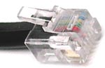 RJ-11 - Short for Registered Jack-11, a four or six-wire connector used primarily to connect telephone equipment in the United States (POTS). The cable itself is called category 1 (Cat 1) and is used for dial-up connections. Modems have rj-11 jacks that connect them to the wall outlet.
 RJ-45 - Short for Registered Jack-45, it is an eight-wire connector used commonly to connect devices on Ethernet LANs. RJ-45 connectors look similar to RJ-11 connectors used for connecting telephone equipment, but they are larger.
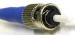 ST - The ST connector is a fiber optic connector which uses a plug and socket which is locked in place with a half-twist bayonet lock. The ST connector was the first standard for fiber optic cabling. ST Connectors are half-duplex.
 SC - The SC connector is a fiber optic connector with a push-pull latching mechanism which provides quick insertion and removal while also ensuring a positive connection. SC Connectors are half-duplex.
 LC - The LC connector is just like a SC connector only it is half the size. Like SC connectors, LC connectors are half-duplex.
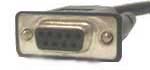 RS-232 - A standard for serial binary data interconnection between a DTE (Data terminal equipment) and a DCE (Data communication equipment). Commonly found in use with bar code scanners, measuring tools, and laboratory instruments are designed to interface to a computer using a standard RS232 serial cable connection. Many of these uses are being replaced with USB enabled devices. The connector is a DB-9 or DB-25 connector.
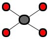 Star - The star topology uses twisted pair (10baseT or 100baseT) cabling and requires that all devices are connected to a hub. Advantages are centralized monitoring, and failures do not affect others unless it is the hub, easy to modify. The disadvantage is that the hub is a single point of failure. If it goes down, there are no communications possible.
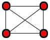 Mesh - In a true mesh topology every node has a connection to every other node in the network. A full mesh provides redundancy in case of a failure between links, but is impractical due the complexity and the expensive amount of cabling required.
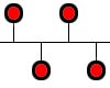 Bus - This topology is an old one and essentially has each of the computers on the network daisy-chained to each other. Packets must pass through all computers on the bus. This type is cheap, and simple to set up, but causes excess network traffic, a failure may affect many users, and problems are difficult to troubleshoot.
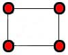 Ring - A ring topology has a physical and logical ring and is used on SONET and FDDI networks (note that Token Ring networks are actually a hybrid star ring topology). Any station can send a packet around the ring but only the station with the token can do so. The token is passed around the ring giving all stations an opportunity to communicate. This is a very fast and simple network. However if any part of the ring goes down, the entire LAN goes down. If there is a problem at a station, it may be difficult to locate it. Ring networks are not very common.
 Point-to-point - This topology generally refers to a connection restricted to two endpoints. Point-to-point is sometimes referred to as P2P (not the same as peer-to-peer file sharing networks), or Pt2Pt, or variations of this. Examples of this topology include RS-232 serial connections as well as laser network connections between buildings.
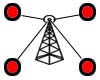 Point-to-Multipoint - Also known as P2MP, this is a method of communication between a series of receivers and transmitters to a central location. The most common example of this is the use of a wireless access point that provides a connection to multiple devices.
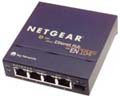 Hub - A physical layer network device used to connect multiple Ethernet devices together. Active hubs act as a repeater and boost the signal in order to allow for it to travel farther, while passive hubs simply pass the signal through. Most hubs have an uplink port that allows them to connect to other hubs, a router, or other network devices.
 Repeater: - A physical layer device that boosts signals in order to allow a signal to travel farther and prevent attenuation. Attentuation is the degradation of a signal as it travels farther from its origination. Repeaters do not filter packets and will forward broadcasts. Both segments must use the same access method, which means that you can't connect a token ring segment to an Ethernet segment. Repeaters can connect different cable types as shown in the image.
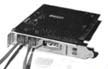 Modem - The modem is a device that converts digital information to analog by MODulating it on the sending end and DEModulating the analog information into digital information at the receiving end. Most modern modems are internal, however, they can be internal or external. External modems are connected to the back of the system board via a RS-232 serial connection. Internal modems are installed in one of the motherboard's PCI or ISA expansion slots depending on the modem. The modem contains an RJ-11 connection that is used to plug in the telephone line. Modems have different transmission modes as follows:
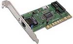 Network Interface Card - A Network Interface Card, often abbreviated as NIC, is an expansion board you insert into a computer so the computer can be connected to a network. Most NICs are designed for a particular type of network, protocol and media, although some can serve multiple networks.
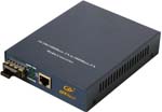 Media Converters - simple networking devices that make it possible to connect two dissimilar media types such as twisted pair with fiber optic cabling. They were introduced to the industry nearly two decades ago, and are important in interconnecting fiber optic cabling-based systems with existing copper-based, structured cabling systems. They are also used in MAN access and data transport services to enterprise customers. Fiber media converters support many different data communication protocols including Ethernet, Fast Ethernet, Gigabit Ethernet, T1/E1/J1, DS3/E3, as well as multiple cabling types such as coax, twisted pair, multi-mode and single-mode fiber optics. Media converter types range from small standalone devices and PC card converters to high port-density chassis systems that offer many advanced features for network management.
 Switch - A switch is a network device that filters and forwards packets between LAN segments and ensures that data goes straight from its origin to its proper destination. Switches remember the address of every node on the network, and anticipate where data needs to go. A switch only operates with the computers on the same LAN. This reduces competition for bandwidth between devices on the network. It isn't smart enough to send data out to the internet, or across a WAN. These functions require a router.
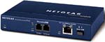 Bridge - Functions the same as a repeater, but can also divide a network in order to reduce traffic problems. A bridge can also connect unlike network segments (ie. token ring and ethernet). Bridges create routing tables based on the source address. If the bridge can't find the source address it will forward the packets to all segments. Bridging methods:
 Wireless Access Point - A Wireless Access Point is a radio frequency transceiver which allows your wireless devices to connect to a network. The WAP usually connects to a wired network, and can relay data between the wireless devices (such as computers or printers) and wired devices on the network. A wireless access point will support up to 32 wireless devices. The range of the wireless signal depends greatly on obstructions such as walls. For more information about wireless standards, see domain 1.7.
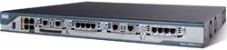 Router - Functioning at the network later of the OSI model, a router is similar to a switch, but it can also connect different logical networks or subnets and enable traffic that is destined for the networks on the other side of the router to pass through. Routers create or maintain a table of the available routes and can be configured to use various routing protocols to determine the best route for a given data packet. Routers can connect networks that use disimilar protocols. Routers also typically provide improved security functions over a switch.
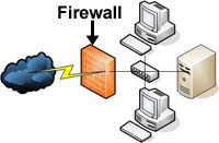 Firewall - Either a hardware or software entity (or a combination of both) that protects a network by stopping network traffic from passing through it. In most cases, a firewall is placed on the network to allow all internal traffic to leave the network (email to the outside world, web access, etc.), but stop unwanted traffic from the outside world from entering the internal network. This is achieved by granting and denying access to resources based on a set of configurable rules.
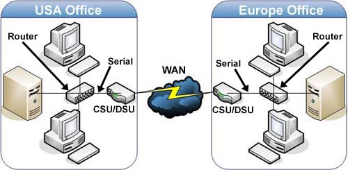
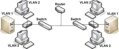
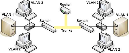
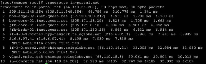
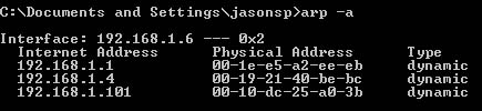
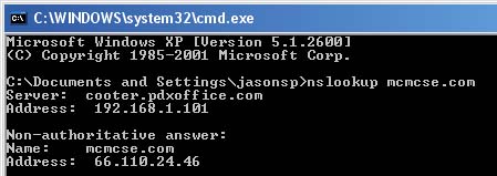
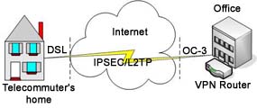 VPN (Virtual Private Network) - A VPN is a network that uses a public telecommunication infrastructure, such as the Internet, to provide remote offices or individual users with secure access to their organization's network. A VPN works by using the shared public infrastructure while maintaining privacy through security procedures and tunneling protocols such as the Layer Two Tunneling Protocol (L2TP) or IPSec. In effect, the protocols, by encrypting data at the sending end and decrypting it at the receiving end, send the data through a "tunnel" that cannot be "entered" by data that is not properly encrypted.